Tuesday, 26 November 2024

TRANSISTORS


TRANSISTORS

  • A transistor is a semiconductor device that contains three regions separated by two distinct PN junctions. The two junctions are EB junction and CB junctions. 
  • The central region is called base. 
  • The two outer regions are called emitter and collector. 
  • There are two types of charge carriers, electrons and holes hence transistor is called bipolar transistor. 
  • Transistor can be viewed as two PN junction diodes arranged back-to-back with base being common to both the diodes. 
  • As soon as the two junctions are formed, majority charge carriers diffuse and form two depletion layers. Depletion layer is narrow at EB junction and wide at CB junction.
There are two types of transistors: 
1.NPN transistor--P-type sandwiched between two N-type. 
2.PNP transistor--N-type sandwiched between two P-type.
FUNCTIONS OF THREE REGIONS IN TRANSISTOR: 
Emitter, Base and Collector are three regions in a transistor. 
Emitter:  
  • It emits charge carriers. 
  • It is heavily doped and has moderate size. 
  • It is located at the one end of transistor. 
Base: 
  • The base controls the flow of charge carriers from emitter to the collector. Therefore, it acts as a gate between emitter and collector. 
  • It has minimum thickness and is lightly doped. 
  • It makes the central region of a transistor. 
Collector: 
  •  It collects the charge carriers coming from the base. 
  • It has largest size with moderate doping. It is moderately doped. 
  •  It is at the other end of a transistor.
Biasing of transistor 
  • The Emitter-Base (EB) junction of transistor is always forward biased, and CollectorBase (CB) junction of transistor is always reverse biased. 
  • Therefore, it works in an active mode. Hence, it transfers current from low resistance region (EB) to high resistance region (CB). 
  • It is seen that almost same current flows through the two junctions. 
  • Thus, the device is called as transistor- the shortened form of transfer resistor


CIRCUIT CONFIGURATION 
COMMON BASE CONFIGURATION


TRANSISTOR ACTION


APPLICATIONS OF TRANSISTOR 
  • It is used in switching electronic circuits.
  • It is used as an amplifier.
  •  It is used in integrated circuits.


HALL EFFECT

HALL EFFECT 
If a metal or a semiconductor carrying a current I is placed in a transverse magnetic field B, a potential difference VH is produced in the direction normal to both the current and magnetic field directions. This phenomenon is called Hall Effect .

Fig: Schematic of Hall Effect Set Up
Applications / importance of Hall Effect 
(i) to determine the type of semiconductor 
(ii) to determine sign of majority charge carriers concentration 
(iii) to determine concentration of majority charge carriers
(iv) to determine mobility of majority charge carriers 
(v) to determine the drift velocity of majority charge carriers.

1) Hall Voltage 
Let us consider a bar of P-type semiconductor crystal and assume the charge carriers to be holes having a charge +e. Let an electric field Ex be applied to the bar which produced a current I in the x-direction in the crystal.
The Current through the semiconductor wafer is given by
Where p is the hole concentration 
             A is the area of cross section of the end face of semiconductor wafer 
             e electrical charge associated with hole 
            vd is the drift velocity of holes
Let a magnetic field B act in the Z-direction. As holes moves in the bar with a velocity, say v, they experience a Lorentz force FL due to the transverse magnetic field B.As a result they deviate sidewise towards the front face of the bar.
        Because of the deflection due to magnetic field, the holes is case of p-type crystal accumulate on front face and make it positively charged while the rare face becomes negatively charged with respect to the front face. Hence a potential VH called the Hall Voltage appears between the front and rare faces.
        The potential builds up in such a way that the electric field EH due to it discourages the further building up of the charges on the faces. The Process of accumulation of charges on front face lasts till the electric field just balances the Lorentz force FL.  
        Once the balance is established the charge accumulation stops and the crystal attains equilibrium states where holes moves parallel to the faces once again.

In the equilibrium state


Wednesday, 12 April 2023

Types of source


Ideal Voltage Source: 

An ideal voltage source is capable to maintain the constant voltage across its terminals. The voltage across the voltage source terminals remains constant and the voltage is independent of the current.  An ideal voltage source must have zero internal resistance. Hence, the voltage across the load will be equal to the voltage across the terminals of the voltage source. 

The fig. 1(a) shows voltage source and 1(b) shows its output characteristic


Practical Voltage Source: 

Voltage Sources having some amount of internal resistances connecting in series is known as Practical Voltage Source. Due to this internal resistance; voltage drop takes place, and it causes the terminal voltage to reduce. The smaller is the internal resistance (r) of a voltage source, the more closer it is to an Ideal Source.


Ideal Current Source

An ideal current source that is capable of providing a constant current output regardless of the load resistance.  An ideal current source is a circuit element that maintains a prescribed current through its terminals regardless of the voltage across those terminals.

  • It produces a constant current value irrespective of the voltage across it.
  • i.e., i=is for all V

currentsource_vi

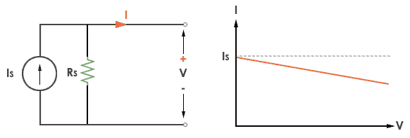
 Practical current source

A practical current source is represented as an ideal current source connected with resistance in parallel.

Practical Current source

The graph represents the current of the current source with respect to time. It is not constant but it also keeps on decreasing as the time passes.

A practical current source is represented as an ideal current source connected with resistance in parallel.

Practical Current source

The graph represents the current of the current source with respect to time. It is not constant but it also keeps on decreasing.


Tuesday, 11 April 2023

electric circuit and ohm law

Electric Circuit

(i)EMF: Electromotive force (emf) is the force that causes an electric current to flow in an electric

circuit.The S.I. Unit of EMF is volt (V).

(ii) Potential difference: Potential difference between two points in an electric circuit is that difference in their electrical state which ends to cause flow of electric current between them.

The S.I. unit of potential difference is volt (V)

(iii) Electric Current: The electric current is defined as the rate of flow of electric charge or electrons,

Its  S. I. unit is Ampere (A).

 (iv) Electric Power: The rate at which work is done in an electric circuit is known as electric power.

  i.e. Electrical power=  


                                                                   Power = voltage x current

P=VI

P = I2R

P = V2/ R

The basic unit of electric power is watt.

One Watt: The power in electric circuit is one watt if a electric potential of 1 volt causes 1 ampere electric current to flow through the circuit.

(v) Electrical Energy: The total amount of work done in an electric circuit is called electrical energy. Electrical Energy = Voltage x Current x time

The unit of electric energy is watt-second

Ohm’s Law 

Ohm's law states that "The potential difference between the two ends of a conductor is directly proportional to the current flowing through it, provided it's temperature and other physical parameters remains unchanged".


 That is, V α I  

V=RI 

where, R is the resistance between these two points.

Voltage= Current× Resistance
V= I×R
V= voltage, I= current and  R= resistance

The SI unit of resistance is ohms and is denoted by Î©

Limitations: Resistance, Temperature, Physical condition should remain constant.


Saturday, 26 November 2022

three phase transformer(core and shell type)

The three phase transformer is mainly classified into two types, i.e., the core type transformer and the shell type transformer.

Core Type Three Phase Transformer

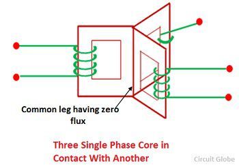
Consider a three single phase core type transformer positioned at 120° to each other as shown in the figure below. If the balanced three-phase sinusoidal voltages are applied to the windings, the fluxes φa, φb and φc will also be sinusoidal and balanced. If the three legs carrying these fluxes are combined, the total flux in the merged leg becomes zero. This leg can, therefore, be removed because it carries the no flux. This structure is not convenient for the core.

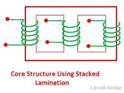
thrre-phase-core-in-contact-with-otherThe core of the three phase transformer is usually made up of three limbs in the same plane. This can be built using stack lamination. The each leg of this core carries the low voltage and high voltage winding. The low voltage windings are insulated from the core than the high voltage windings.

core-structure-using-stacked-laminationsThe low windings are placed next to the core with suitable insulation between the core and the low voltage windings. The high voltage windings are placed over the low voltage windings with suitable insulation between them. The magnetic paths of the leg a and c are greater than that of leg b, the construction is not symmetrical, and there is a resultant imbalance in the magnetising current.

Shell type Three Phase Transformer

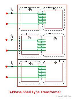
The shell type 3-phase transformer can be constructed by stacking three single phase shell transformer as shown in the figure below. The winding direction of the central unit b is made opposite to that of units a and c. If the system is balanced with phase sequence a-b-c, the flux will also be balanced

three-phase-shell-type-transformerThe magnitude of this combined flux is equal to the magnitude of each of its components. The cross section area of the combined yoke is same as that of the outer leg and top and bottom section of the yoke. The imbalance in the magnetic path has very little effect on the performance of the three shell-type transformers. 

Three-Phase Transformer - Construction & Working Principle

Normally generation of power is usually at 3-phase from 11kV to 33kV. Transmission of generated power to the load centers is accomplished at higher voltages of 132kV to 400kV (or 700kV). For transmitting (sending end) the generated 3-phase power at such higher voltages it is essential to have a step-up 3-phase transformer.

Next, at load centers, the transmitted 3-phase power has to be stepped down to 33kV, 11kV, 440V, or 230V and distributed to the various consumers. For distributing the electrical power again it is essential to have a 3-phase step-down transformer.

Earlier years ago, the construction of a 3-phase transformer is by suitably interconnecting three single-phase transformers. But, nowadays instead of using three different single-phase transformers the whole primary and secondary windings of three transformers are built into a single core structure.

This construction is gaining more popularity because of its better improvement in design and manufacture and better acquaintance of operation. Let us see the construction of a 3-phase transformer.

Construction of Three-Phase Transformer :

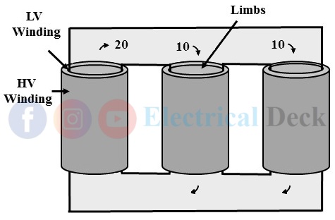
Similar to the single-phase transformer the core of the three-phase transformer is constructed either in core type or shell type. The LV and HV windings of the 3-phases are placed on the three limbs of the core.

Core Type 3-Phase Transformer :

In a core type 3-phase transformer, the core is divided into three limbs in which each limb carries both high-voltage HV and low-voltage LV windings of the three phases. The flux produced by the primary ampere-turns will be linked by the secondary windings.

The primary and secondary of each phase on each limb is placed such that the LV winding is placed over the core limb and HV winding is placed on the LV winding. The main reason to place LV winding next or nearer to the core is the amount of insulation required is low to insulate the LV winding from the core as shown below.

Three-Phase Transformer

The three core limbs of the three-phase winding are 120° apart. In a core type three-phase transformer at any instant, one limb out of three will act as a return path for the magnetic flux of the other two limbs.

The above represents the direction and magnitude of fluxes of a particular instant. It is seen that the sum of fluxes in the two limbs (downward direction) is equal to the flux in one limb (upward direction) that acts as a return path.

Shell Type 3-Phase Transformer :

A 3-phase shell type transformer can be combined with three single-phase shell-type transformers as shown in the below figure.

Three-Phase Transformer

The shell-type core construction of a three-phase transformer is less commonly used. It consists of five limbs and the core surrounds the windings made on three limbs. The other two limbs (between phases) hold the three limbs as a one-unit and also provides a return path for the fluxes.

The whole construction is similar when three single-phase transformers are put side by side. Compared to the core type structure each phase has its independent magnetic circuit and return path for flux. Hence three phases are more independent in shell-type construction.

The entire core structure (either core or shell type) with windings is placed inside the transformer tank filled with oil. The winding connections of the three phases are made inside the transformer tank. The terminals of primaries and secondaries of three phases are taken out of the tank through bushings for external connections. The most commonly used three-phase transformer winding connections are,

Working Principle of Three-Phase Transformer :

The basic working principle of a three-phase transformer is the same as a single-phase transformer i.e., on mutual induction. The alternating supply is given to the primary windings and it induces an emf in the secondary winding. The amount of induced emf depends upon the number of secondary turns (either can be a step-up or a step-down transformer).

Advantages of Three-Phase Transformer :

Advantages of a three-phase transformer over three single-phase transformers are,
  • A three-phase transformer has considerably less weight.
  • Three-phase transformer occupies less floor area.
  • Three-phase transformer costs 15% less than three single-phase transformers of equal ratings.
  • Only one unit (3-phase transformer) is to be handled.
  • The busbars, switchgear, and protection equipment for a single unit transformer are less which makes the unit more economical.

Disadvantages of Three-Phase Transformer :

In a three-phase transformer, the three windings of three phases form one unit. This makes the whole transformer shut down in case of any fault in any one of the phases and it can be replaced or repaired. But, in the case of three single-phase transformers, the faulty phase transformer gets isolated and the system can run on open-delta with reduced efficiency.

TRANSISTORS

TRANSISTORS A transistor is a semiconductor device that contains three regions separated by two distinct PN junctions. The two junctions are...

Translate