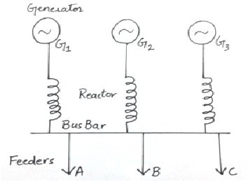
- Generator Reactors:
When reactor is connected between bus bar and generator, it is called a generator reactor. This reactor can also be connected in series with the generator. When a new generator is connected with an old generator, a reactor is added in series with the old generator to provide protection. The value of this reactor depends on the impedance of that generator. Its pu value should be 0.05 or 0.06. See the following figure:
Disadvantages:
- The fault on a feeder disconnects the supply of other feeders also.
- After removing the faulty feeder, the generator has to be synchronized again.
- During normal operation, full load current passes through the reactor which causes continuous power loss.
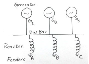
Feeder reactors:
It is when a reactor is connected in series with a feeder as shown in the figure:
Usually short circuits occur on feeders therefore, feeder reactors are very important. In the absence of feeder reactors, if a fault occurs on the nearest generating station, the bus bar voltage will be reduced to zero and the connected generators will lose their synchronism.
Advantages:
- The voltage drop across a reactor during faulty conditions will not affect the voltage of bus bar, therefore, there are less chances of losing synchronism.
- A fault on a feeder will not affect any other feeder.
Disadvantages:
- Every feeder needs a reactor hence the number or reactors increases.
- If the number of generators increases, then the size of the reactor should also be increased.
- During normal operation, full load current passes through the reactor which causes continuous power loss.
Reactors should be connected according to the power factor of the feeders to regulate proper voltages. Feeder reactance should be about 0.05 to 0.12 pu.
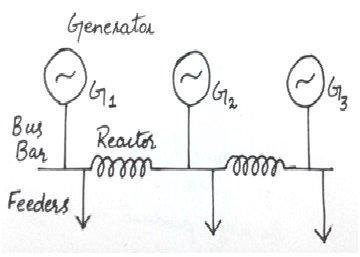
- Bus bar reactors:
These reactors are connected with bus bars. Bus bar reactors divide the bus bar in smaller sections. If the voltage level is same, no current passes through these reactors and every section act as an independent bus bar.
If a fault occurs on a section of bus bar, the reactor prevents the fault from reaching to other sections and only the fault section is affected. Hence a bus bar should be large enough to protect the system but it should not disturb the synchronism of the system. A reactor which drops the voltage about 30 to 50% at full current is suitable. However the reactance of a sinlge bus bar reactor should be about 0.3 to 0.5 pu.
The following methods describe how to decrease the continuous voltage drop and power losses in case of feeder and generator reactors:
- Ring system:
In this system, a bus bar is divided into different sections and these sections are connected together through a reactor. Each feeder is fed by a separate generator and during normal operation each generator supplies power to its respective load due to which very less power loss occurs in the reactors.
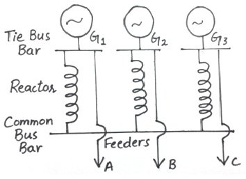
 2. Tie bar system:
In this system, the generators are connected to a common bus bar through the reactors and feeders are fed through the generator side of the reactors. This system is very efficient in case of larger systems. The reactance of the reactors in this case is half as compared to the ring system reactance.
Advantages and disadvantages:
This system is more flexible. By increasing the number of sections, the switch gears work efficiently without any modifications in the system.
But this system is complex and requires an additional bus i.e, tie bar.
