Magnetic Circuit

Magnetic flux
The magnetic lines of force passing through a magnetic circuit is known as magnetic flux. It is denoted by a symbol ϕ and given by a formula ϕ = BA, where B is the magnetic flux density and A is the area of the cross-section in m2. The unit of magnetic flux is weber.
Magneto-motive force
Magneto-motive force or MMF is the cause for producing the magnetic flux. The MMF in a magnetic circuit depends on the number of turns(N) and the amount of current(I) flowing through it.
It is given by a formula, MMF = NI and its unit is ampere turns.
Magnetic flux density
It is the amount of magnetic flux per unit area at right angles to the flux. The unit of magnetic flux density is weber/m2 and denoted by B. The formula is given by,
![\[B=\frac{\phi}{a}\]](https://www.electrically4u.com/wp-content/ql-cache/quicklatex.com-685666348a1f142f1f33503384681758_l3.png?ezimgfmt=rs:51x36/rscb4/ng:webp/ngcb4 "Rendered by QuickLaTeX.com")
Magnetic field intensity
Magnetizing force or Magnetic field intensity or magnetic field strength is the MMF required to magnetize a unit length of the magnetic flux path. The unit of magnetic field intensity is AT/m and is denoted by H.
![\[H=\frac{NI}{l}\]](https://www.electrically4u.com/wp-content/ql-cache/quicklatex.com-55646d5715d2ffb6a1b280726e88af46_l3.png?ezimgfmt=rs:68x37/rscb4/ng:webp/ngcb4 "Rendered by QuickLaTeX.com")
Reluctance
It is the opposition that the magnetic circuit offers for the flow of magnetic flux. We can also define the reluctance as the ratio of magneto-motive force to the magnetic flux. It is denoted by S and its unit is ampere-turns per weber.
![\[Reluctance(S) = \frac{MMF}{flux} \]](https://www.electrically4u.com/wp-content/ql-cache/quicklatex.com-78f4af045dfe4216c320313bffa61b41_l3.png?ezimgfmt=rs:192x41/rscb4/ng:webp/ngcb4 "Rendered by QuickLaTeX.com")
Permeance
Permeance is the reciprocal of reluctance. The ease with which the flux can pass through the material is known as permeance. Weber/AT is the unit of permeance.
![\[Permeance = \frac{1}{reluctance}\]](https://www.electrically4u.com/wp-content/ql-cache/quicklatex.com-627be91fe6563107a95019c01194ac17_l3.png?ezimgfmt=rs:199x36/rscb4/ng:webp/ngcb4 "Rendered by QuickLaTeX.com")
Permeability
It is the measure of the resistance of a material against the formation of a magnetic field. In simple words, the permeability of material means its conductivity for magnetic flux. The reciprocal of magnetic permeability is magnetic reluctivity. Greater permeability, greater is its conductivity.
Magnetic permeability is represented by a greek letter μ. It is given by a formula,
![\[ \mu = \frac{B}{H}\]](https://www.electrically4u.com/wp-content/ql-cache/quicklatex.com-cb4f0d24b3cf2e074f1af2ab3b09a687_l3.png?ezimgfmt=rs:53x37/rscb4/ng:webp/ngcb4 "Rendered by QuickLaTeX.com")
Relative permeability
It is the ratio of flux density of a magnetic material to the flux density produced in air by the same magnetizing force.
The formula for relative permeability is,
![\[ \mu_r = \frac{\mu}{\mu_0}\]](https://www.electrically4u.com/wp-content/ql-cache/quicklatex.com-ecd4cbe0ce33acade514771538d7c1ac_l3.png?ezimgfmt=rs:63x36/rscb4/ng:webp/ngcb4 "Rendered by QuickLaTeX.com")
where μr – relative permeability of the magnetic material.
μ0 – absolute permeability of air or vacuum.
μ – absolute permeability of the magnetic material.
Analogy between Magnetic circuit and Electric Circuit
| Magnetic Circuit | Electric Circuit |
|---|---|
| A closed path for a magnetic flux forms a magnetic circuit. | A closed path for an electric current form an electric circuit. |
| Magnetic flux does not flow in a magnetic circuit. | Electric current always flows in an electric circuit. |
| MMF is the cause for producing flux. | EMF is the cause for producing current. |
| Weber is the unit of flux. | Ampere is the unit of current. |
| Reluctance opposes the flow of flux. | Resistance opposes the flow of current. |
| Flux density, | Current density, |
| Magnetic field intensity, | Electric field intensity, |
| Magnetic flux lines flow from the North pole to the South pole. | Electric current flows from the positive to negative terminal. |
![\[Flux = \frac{mmf}{reluctance}\]](https://www.electrically4u.com/wp-content/ql-cache/quicklatex.com-4542a37c3445e21615341693e81ccd8a_l3.png?ezimgfmt=rs:148x36/rscb4/ng:webp/ngcb4 "Rendered by QuickLaTeX.com")
![\[Current= \frac{emf}{resistance}\]](https://www.electrically4u.com/wp-content/ql-cache/quicklatex.com-888fbdc3ec00628105dae6ff2f98dc0c_l3.png?ezimgfmt=rs:174x36/rscb4/ng:webp/ngcb4 "Rendered by QuickLaTeX.com")
![\[Reluctance= \frac{l}{\mu_0 \mu_r a}\]](https://www.electrically4u.com/wp-content/ql-cache/quicklatex.com-764107b649c7b7d7249c854080802188_l3.png?ezimgfmt=rs:160x40/rscb4/ng:webp/ngcb4 "Rendered by QuickLaTeX.com")
![\[Resistance= \frac{\rho l}{a}\]](https://www.electrically4u.com/wp-content/ql-cache/quicklatex.com-6a2be2ca80742a5c9a2de12227d1d181_l3.png?ezimgfmt=rs:128x36/rscb4/ng:webp/ngcb4 "Rendered by QuickLaTeX.com")
![\[Conductance= \frac{1}{resistance}\]](https://www.electrically4u.com/wp-content/ql-cache/quicklatex.com-5eece579be16edf7dbe7b8c63e48eaca_l3.png?ezimgfmt=rs:210x36/rscb4/ng:webp/ngcb4 "Rendered by QuickLaTeX.com")
![\[B = \frac{\phi}{a}\]](https://www.electrically4u.com/wp-content/ql-cache/quicklatex.com-c2c5f4b3d2602d031e2f498677f5006e_l3.png?ezimgfmt=rs:51x36/rscb4/ng:webp/ngcb4 "Rendered by QuickLaTeX.com")
![\[J = \frac{I}{a}\]](https://www.electrically4u.com/wp-content/ql-cache/quicklatex.com-a1e21908923895641312d237d6ab8c01_l3.png?ezimgfmt=rs:46x37/rscb4/ng:webp/ngcb4 "Rendered by QuickLaTeX.com")
![\[H = \frac{NI}{l}\]](https://www.electrically4u.com/wp-content/ql-cache/quicklatex.com-e40f5149da50048b8ea256058b1c9a15_l3.png?ezimgfmt=rs:68x37/rscb4/ng:webp/ngcb4 "Rendered by QuickLaTeX.com")
![\[E = \frac{V}{d}\]](https://www.electrically4u.com/wp-content/ql-cache/quicklatex.com-2d2b8acdfdde9a25e32ac95de27404d3_l3.png?ezimgfmt=rs:55x37/rscb4/ng:webp/ngcb4 "Rendered by QuickLaTeX.com")
Leakage Flux And Fringing
Leakage flux is defined as the magnetic flux which does not follow the particularly intended path in a magnetic circuit.
Taking an example of solenoid you can explain the leakage flux and the fringing both.
When a current is passed through a solenoid, magnetic flux is produced by it.
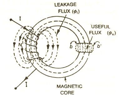
Most of the flux is set up in the core of the solenoid and passes through the particular path that is through the air gap and is utilised in the magnetic circuit. This flux is known as Useful flux φu.
As practically it is not possible that all the flux in the circuit follows a particularly intended path and sets up in the magnetic core and thus some of the flux also sets up around the coil or surrounds the core of the coil, and is not utilised for any work in the magnetic circuit. This type of flux which is not used for any work is called Leakage Flux and is denoted by φl.
Therefore, the total flux Φ produced by the solenoid in the magnetic circuit is the sum of the leakage flux and the useful flux and is given by the equation shown below:
Leakage coefficient
The ratio of the total flux produced to the useful flux set up in the air gap of the magnetic circuit is called a leakage coefficient or leakage factor. It is denoted by (λ).
Fringing
The useful flux when sets up in the air gap, it tends to bulge outward at (b and b’) as shown in above figure, because of this bulging, the effective area of the air gap increases and the flux density of the air gap decreases. This effect is known as Fringing.
Fringing is directly proportional to the length of the air gap that means if the length increases the fringing effect will also be more and vice versa.
