Ferranti Effect
Under the Ferranti effect, no-load and light load conditions make the receiving end voltage greater than the sending end voltage. If the receiving voltage exceeds the limit, it damages the connected load, which is why reducing the Ferranti effect is essential.
The influence of inductance and capacitance on the receiving end voltage of AC transmission lines at light load conditions is the root cause of the Ferranti effect.
Shunt compensation and series compensation can be employed in transmission lines to reduce the Ferranti effect.
Electrical transmission lines are subjected to various effects, including the Ferranti effect
Electrical transmission lines are subjected to various effects such as the skin effect, proximity effect, corona discharge, and the Ferranti effect. Specific conditions and circumstances lead to these effects in the transmission line.
The influence of inductance and capacitance on the receiving end voltage of AC transmission lines at light load conditions is the root cause of the Ferranti effect. Under this effect, no-load and light load conditions make the receiving end voltage greater than the sending end voltage. If the receiving voltage exceeds the limit, it damages the connected load. This is why it is so essential to learn how to reduce the Ferranti effect, which is what we will be discussing in this article.
The Ferranti Effect in Transmission Lines
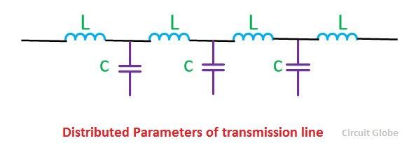
Transmission lines can be classified as short, medium, and long. Among these classifications, the long transmission line is composed of the highest amount of capacitance and inductance distributed along the length.
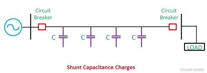
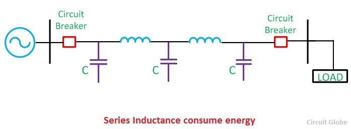
Consider a nominal pi model of a long transmission line. When the long transmission line is at no load or lightly loaded, the distributed capacitance of the transmission line draws more current. The capacitor charging current through the distributed inductance of the transmission line creates a voltage drop across it (which is in-phase with the sending end voltage). The resultant receiving end voltage becomes greater than the sending end voltage. This phenomenon of overvoltage in a transmission line’s receiving end at light load conditions is called the Ferranti effect. Under the Ferranti effect, the reactive power generated is more than the reactive power absorbed, and this causes the voltage to rise in the receiving end.
The Disadvantages of the Ferranti Effect
The Ferranti effect is an undesirable effect in electrical AC power systems. All power systems follow the specifications for receiving end voltage with some tolerance level. The loads connected to the system are usually rated for this voltage and safely operate under normally loaded conditions.
Potential Damage Caused by the Ferranti Effect
However, under light load conditions, the Ferranti effect introduces temporary overvoltage at the receiving end. These overvoltages are capable of limiting the performance of transmission lines and damaging the loads and equipment connected to the receiving end. The damage of voltage-sensitive process controls, controllers, and automated systems leads to a loss of utility and temporary shutdowns. The impact of monetary losses associated with the Ferranti effect can also be extremely damaging to a project’s budget.
How to Reduce the Ferranti Effect
High voltage at the receiving end of a transmission line is hazardous to equipment and personnel. So, how do we reduce the Ferranti effect? Here are a few ways to reduce this effect.
Protection Systems and the Ferranti Effect
Usually, switchgear and protection systems in transmission lines are designed for sending end voltage. When a rise in voltage is experienced in the transmission line due to the Ferranti effect, circuit breakers and other protection devices operate and break the circuit for safety. However, bringing the transmission line switchgears back to a normal state requires maintenance. Reactive compensation in a transmission line is essential, as the reactive power generated is greater than that which is absorbed.
Passive Compensation
Shunt reactors and series capacitors can reduce the voltage rise if placed at suitable locations in the transmission line. The transmission line inductance can be compensated by connecting series capacitors and the capacitance of the line can be controlled by placing shunt reactors. The series capacitors are placed along the transmission line length, reducing the effective reactance (inductive reactance and capacitive reactance) of the transmission line. The compensation of the transmission line inductance by inserting capacitors in series results in low voltage at the receiving end compared to the sending end voltage.
Shunt reactors are positioned at the ends of the lines and at the junctions where two or more lines meet. Shunt reactors can also be connected across the tertiary winding of the power transformers in electrical transmission systems. The shunt reactors are constructed in the same way as power transformers, with one difference—non-magnetic gaps between the packets of reactor core steel. In 3-phase systems, 3-limbed and 5-limbed core reactors are used alternatively. The neutral of these reactors can be left unearthed, directly earthed, or earthed through the earthing reactor.
Active Compensation
The Ferranti effect can be mitigated by using FACTS devices for reactive power compensation. Thyristor-controlled reactors and thyristor switched capacitors can be connected to the transmission line, and the proper switching of these devices can help control the Ferranti effect on transmission lines. Compensators such as STATCOM, dynamic voltage restorers, and unified power flow controllers (UPFC) can be introduced into electrical transmission systems for reactive power compensation, which aids in the reduction of the Ferranti effect.
There are passive and active solutions available when it comes to the question of how to reduce the Ferranti effect on transmission lines. Cadence’s software can assist power system engineers in choosing the most effective method of compensation for the given transmission system.

![\[B=\frac{\phi}{a}\]](https://www.electrically4u.com/wp-content/ql-cache/quicklatex.com-685666348a1f142f1f33503384681758_l3.png?ezimgfmt=rs:51x36/rscb4/ng:webp/ngcb4 "Rendered by QuickLaTeX.com")
![\[H=\frac{NI}{l}\]](https://www.electrically4u.com/wp-content/ql-cache/quicklatex.com-55646d5715d2ffb6a1b280726e88af46_l3.png?ezimgfmt=rs:68x37/rscb4/ng:webp/ngcb4 "Rendered by QuickLaTeX.com")
![\[Reluctance(S) = \frac{MMF}{flux} \]](https://www.electrically4u.com/wp-content/ql-cache/quicklatex.com-78f4af045dfe4216c320313bffa61b41_l3.png?ezimgfmt=rs:192x41/rscb4/ng:webp/ngcb4 "Rendered by QuickLaTeX.com")
![\[Permeance = \frac{1}{reluctance}\]](https://www.electrically4u.com/wp-content/ql-cache/quicklatex.com-627be91fe6563107a95019c01194ac17_l3.png?ezimgfmt=rs:199x36/rscb4/ng:webp/ngcb4 "Rendered by QuickLaTeX.com")
![\[ \mu = \frac{B}{H}\]](https://www.electrically4u.com/wp-content/ql-cache/quicklatex.com-cb4f0d24b3cf2e074f1af2ab3b09a687_l3.png?ezimgfmt=rs:53x37/rscb4/ng:webp/ngcb4 "Rendered by QuickLaTeX.com")
![\[ \mu_r = \frac{\mu}{\mu_0}\]](https://www.electrically4u.com/wp-content/ql-cache/quicklatex.com-ecd4cbe0ce33acade514771538d7c1ac_l3.png?ezimgfmt=rs:63x36/rscb4/ng:webp/ngcb4 "Rendered by QuickLaTeX.com")
![\[Flux = \frac{mmf}{reluctance}\]](https://www.electrically4u.com/wp-content/ql-cache/quicklatex.com-4542a37c3445e21615341693e81ccd8a_l3.png?ezimgfmt=rs:148x36/rscb4/ng:webp/ngcb4 "Rendered by QuickLaTeX.com")
![\[Current= \frac{emf}{resistance}\]](https://www.electrically4u.com/wp-content/ql-cache/quicklatex.com-888fbdc3ec00628105dae6ff2f98dc0c_l3.png?ezimgfmt=rs:174x36/rscb4/ng:webp/ngcb4 "Rendered by QuickLaTeX.com")
![\[Reluctance= \frac{l}{\mu_0 \mu_r a}\]](https://www.electrically4u.com/wp-content/ql-cache/quicklatex.com-764107b649c7b7d7249c854080802188_l3.png?ezimgfmt=rs:160x40/rscb4/ng:webp/ngcb4 "Rendered by QuickLaTeX.com")
![\[Resistance= \frac{\rho l}{a}\]](https://www.electrically4u.com/wp-content/ql-cache/quicklatex.com-6a2be2ca80742a5c9a2de12227d1d181_l3.png?ezimgfmt=rs:128x36/rscb4/ng:webp/ngcb4 "Rendered by QuickLaTeX.com")
![\[Conductance= \frac{1}{resistance}\]](https://www.electrically4u.com/wp-content/ql-cache/quicklatex.com-5eece579be16edf7dbe7b8c63e48eaca_l3.png?ezimgfmt=rs:210x36/rscb4/ng:webp/ngcb4 "Rendered by QuickLaTeX.com")
![\[B = \frac{\phi}{a}\]](https://www.electrically4u.com/wp-content/ql-cache/quicklatex.com-c2c5f4b3d2602d031e2f498677f5006e_l3.png?ezimgfmt=rs:51x36/rscb4/ng:webp/ngcb4 "Rendered by QuickLaTeX.com")
![\[J = \frac{I}{a}\]](https://www.electrically4u.com/wp-content/ql-cache/quicklatex.com-a1e21908923895641312d237d6ab8c01_l3.png?ezimgfmt=rs:46x37/rscb4/ng:webp/ngcb4 "Rendered by QuickLaTeX.com")
![\[H = \frac{NI}{l}\]](https://www.electrically4u.com/wp-content/ql-cache/quicklatex.com-e40f5149da50048b8ea256058b1c9a15_l3.png?ezimgfmt=rs:68x37/rscb4/ng:webp/ngcb4 "Rendered by QuickLaTeX.com")
![\[E = \frac{V}{d}\]](https://www.electrically4u.com/wp-content/ql-cache/quicklatex.com-2d2b8acdfdde9a25e32ac95de27404d3_l3.png?ezimgfmt=rs:55x37/rscb4/ng:webp/ngcb4 "Rendered by QuickLaTeX.com")