Monday 18 April 2022

Design of Lighting Schemes

 i. Illumination Level:

This is the most vital factor because a sufficient illumination is the basic means whereby we are able to see our surroundings.

For each type of work there is a range of brightness most favourable to output i.e. which causes minimum fatigue and gives maximum output in terms of quality depends upon:

(i) The size of the objects to be seen and its distance from the observer. Greater the distance of the object from observer and smaller the size of the object, greater will be the illumination required for its proper perception and

(ii) Contrast between the object and back-ground-greater the contrast between the colour of the object and its background, greater will be the illumination required to distinguish the object properly. Objects which are seen for longer duration of time required more illumination than those for casual work. Similarly moving objects required more illumination than those for stationary objects.

ii. Uniformity of Illumination:

The human eye adjusts itself automatically to the brightness within the field of vision. If there is a lack of uniformity, pupil or iris of the eye has to adjust more frequently and thus fatigue is caused to the eye and productivity is reduced. It has been found that visual performance is best if the range of brightness within the field of vision is not greater than 3:1, which can be achieved by employing general lighting.

iii. Shadows:

In lighting installations, formation of long and hard shadows causes fatigue of eyes and therefore is considered to be a shortcoming. Complete absence of shadows altogether again does not necessarily mean an ideal condition of lighting instillations. Contrary, perhaps to popular opinion, a certain amount of shadow is desirable in artificial lighting as it helps to give shape to the solid objects and makes them easily recognised.

iv. Glare:

It may be direct or reflected i.e. it may come direct from the light source or it may be reflected brightness such as from a desk top, nickeled machine parts, or calendared paper.

Direct glare from a source of light is more common, and is more often a hindrance to vision. A glance at the sun proves that an extremely bright light source causes acute eye discomfort. Reflected glare is glare which comes to the eyes as glint or reflection of the light source in some polished surface.

v. Mounting Height:

In case of direct lighting it depends upon the type of building and type of lighting scheme employed. For rooms of large floor area, the luminaries should be mounted close to ceiling as possible. In case of indirect and semi-indirect lighting, it would be desirable to suspend luminaries enough down from ceiling to give uniform illumination.

vi. Spacing of Luminaries:

The distance of light source from the wall should be equal to one half the distances between two adjacent light sources. The distance between light fittings should not exceed 1.5 times the mounting height.

Different lighting schemes

 Different lighting schemes may be classfied as:

(i) direct lighting, (ii) indirect lighting, (iii) semi-direct lighting, (iv) semi-indirect lighting, and (v) general diffusing systems.
Lighting


(i) Direct Lighting
As the name indicates, in the form of lighting, the light from the source falls directly on the object or the surface to be illuminated. It is most commonly used type of lighting scheme. In this lighting scheme more than 90 percent of total light flux is made to fall directly on the working plane with the help of deep reflectors. Though it is most efficient but causes hard shadows and glare. It is mainly used for industrial and general out-door lighting.

direct lighting

(ii) Indirect Lighting

In this light scheme more than 90 percent of total light flux is thrown upwards to the ceiling for diffuse re­flection by using inverted or bowl reflectors. In such a system the ceiling acts as the light source, and the glare is reduced to mini­mum. The resulting illumination is softer and more diffused, the shadows are less prominent and the appearance of the room is much improved over that which results from direct lighting. It is used for decoration purposes in cinemas theatres and hotels etc. and in workshops where large machines and other obstructions would cause trouble some shadows of direct lighting is employed.


Indirect Lighting

(iii) Semi-direct System

In this lighting scheme 60 to 90 percent of the total light flux is made to fall downwards directly with the help of semi-direct reflectors, remaining light is used to illuminate the ceiling and walls. Such a lighting system is best suited to rooms with high ceilings where a high level of uniformally distributed illumination is desirable. Glare in such units is avoided by employing diffusing globed which not only improve the brightness towards the eye but improve the efficiency of the systems with reference to working place.


Semi-Direct Lighting

(iv) Semi-indirect Lighting

In this lighting scheme 60 to 90 percent of total light flux is thrown upwards to the ceiling for diffuse reflection and the rest reaches the working plane directly except for some absorption by the bowl. This lighting scheme is with soft shadows and glare free. It is mainly used for indoor light decoration purposes.


Semi-Indirect Lighting

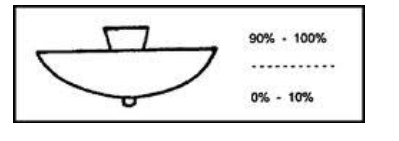
(v) General Diffusing System
In this system, luminaries are employed which have almost equal light distribution downwards and upwards.


Saturday 16 April 2022

ADVANTAGES OF PER UNIT SYSTEM


PER UNIT SYSTEM

The per-unit system expressed the voltages, currents, powers, impedances, and other electrical quantities basis by the equation:

Quantity per unit (pu) = Actual value/ Base value of quantity

ADVANTAGES OF PER UNIT SYSTEM

  1. While performing calculations, referring quantities from one side of the transformer to the other side serious errors may be committed. This can be avoided by using per unit system.
  2. Per unit impedances of electrical equipment of similar type usually lie within a narrow range, when the equipment ratings are used as base values.
  3. Manufacturers usually specify the impedances of machines and transformers in per unit or percent of name plate ratings.
  4. Transformers can be replaced by their equivalent series impedances.
  5. Reduced calculations in three-phase systems.
  6. For apparatus of the same general type the p.u. and volt drops or losses are in the same order, regardless of size.

PER UNIT CONVERSION PROCEDURE OF SINGLE PHASE

  1. Pick a VA base for the entire system, Sbase
  2. Pick a voltage base for each different voltage level, Vbase.
  3. Voltage bases are related by transformer turns ratios.
  4. Voltages are line to neutral.
  5. Calculate the impedance base, Zbase = (Vbase)2/Sbase
  6. Calculate the current base, Ibase =Vbase/Zbase
  7. Convert actual values to per unit
  8. Convert to per unit (p.u.) (many problems are already in per unit)
  9. Solve
  10. Convert back to actual as necessary

Friday 8 April 2022

 FLUORESCENT LAMP (LOW-PRESSURE MERCURY VAPOR LAMP)

Fluorescent lamp is a hot cathode low-pressure mercury vapor lamp;

Construction 

It consists of a long horizontal tube, The tube contains small quantity of argon gas and certain amount of mercury, at a pressure of 2.5 mm of mercury. The construction of fluorescent lamp is shown in Fig.  Normally, low-pressure mercury vapor lamps suffer from low efficiency and they produce an objectionable colored light. Such drawback is overcome by coating the inside of the tube with fluorescent powders. They are in the form of solids, which are usually knows as phosphors.

A glow starter switch contains small quantity of argon gas, having a small cathode glow lamp with bimetallic strip is connected in series with the electrodes, which puts the electrodes directly across the supply at the time of starting. A choke is connected in series that acts as ballast when the lamp is running, and it provides a voltage impulse for starting. A capacitor of 4μF is connected across the starter 

 Working 

At the time of starting, When supply is switched on, the starter terminals are open circuited and full supply voltage appeared across these terminals, due to low resistance of electrodes and choke coil. The small quantity of argon gas gets ionized, which establishes an arc with a starting glow. This glow warms up the bimetallic strip thus glow starts gets short circuited. Hence, the two electrodes come in series and are connected across the supply voltage. Now, the two electrodes get heated and start emitting electrons due to the flow of current through them. These electrons collide with the argon atoms present in the long tube discharge that takes place through the argon gas. So, in the beginning, the lamp starts conduction with argon gas as the temperature increases, the mercury changes into vapor form and takes over the conduction of current. In the mean time, the starter potential reaches to zero and the bimetallic strip gets cooling down. As a result, the starter terminals will open. This results breaking of the series circuit. A very high voltage around 1,000 V is induced,  this induced voltage is quite sufficient to break down the long gap. Thus, more number of electrons collide with argon and mercury vapor atoms. The excited atom of mercury gives UV radiation, which fall on  fluorescent material thus emitted light.

Advantages of fluorescent lamp 
The fluorescent lamp has the following advantages:
 o High efficiency.
 o The life of the lamp is three times of the ordinary filament lamp. 
o The quality of the light obtained is much superior. 
o Less chances of glare.
 o These lamps can be mounted on low ceiling, where other light sources would be unsatisfactory. 

disadvantages: 
o The initial cost is high because of choke and starter. 
o The starting time as well as the light output of the lamp will increases because of low ambient temperature.
 o Because of the presence of choke, these lamps suffer from magnetic humming and may cause disturbance.
 o The stroboscopic effect of this lamp is objectionable.


Thursday 7 April 2022

Illumination

 Nature of light 

Light is a form of electromagnetic energy radiated from a body and human eye is capable of receiving it. Light is a prime factor in the human life as all activities of human being ultimately depend upon the light.

TERMS USED IN ILLUMINATION 

The following terms are generally used in illumination. 

Color

 The energy radiation of the heated body is monochromatic, i.e. the radiation of only one wavelength emits specific color. The wavelength of visible light lies between UNIT 1 4,000 and 7,500 Ã…. The color of the radiation corresponding to the wavelength is shown in Fig. 6.1. 

Light: 

It is defined as the radiant energy from a hot body that produces the visual sensation upon the human eye. It is expressed in lumen-hours and it analogous to watthours, which denoted by the symbol ‘Q’.

 Luminous flux: 

It is defined as the energy in the form of light waves radiated per second from a luminous body. It is represented by the symbol ‘φ’ and measured in lumens. 

Ex: Suppose the luminous body is an incandescent lamp. 

The total electrical power input to the lamp is not converted to luminous flux, some of the power lost through conduction, convection, and radiation, etc. Afraction of the remaining radiant flux is in the form of light waves lies in between the visual range of wavelength, i.e. between 4,000 and 7,000 Ã…, as shown in Fig

Solid angle 

Solid angle is the angle subtended at a point in space by an area, i.e., the angle enclosed in the volume formed by numerous lines lying on the surface and meeting at the point (Fig. 6.5). It is usually denoted by symbol ‘ω’ and is measured in steradian.


Luminous intensity

 Luminous intensity in a given direction is defined as the luminous flux emitted by the source per unit solid angle
 Luminous flux emitting from the source
It is denoted by the symbol ‘I’ and is usually measured in ‘candela’. Let ‘F’ be the luminous flux crossing a spherical segment of solid angle ‘ω’. Then luminous intensity I =d@/dt lumen/steradian or candela.

Lumen: 

It is the unit of luminous flux. It is defined as the luminous flux emitted by a source of one candle power per unit solid angle in all directions. 
Lumen = candle power of source × solid angle. Lumen = CP × Ï‰ 
Total flux emitted by a source of one candle power is 4Ï€ lumens. 

Candle power (CP) 

The CP of a source is defined as the total luminous flux lines emitted by that source in a unit solid angle.

Illumination

 Illumination is defined as the luminous flux received by the surface per unit area. It is usually denoted by the symbol ‘E’ and is measured in lux or lumen/m2 or meter candle or foot candle. 

Lux or meter candle

 It is defined as the illumination of the inside of a sphere of radius 1 m and a source of 1 CP is fitted at the center of sphere.

Brightness

 Brightness of any surface is defined as the luminous intensity pen unit surface area of the projected surface in the given direction. It is usually denoted by symbol ‘L’. If the luminous intensity of source be ‘I’ candela on an area A, then the projected area is Acos θ. 

Mean horizontal candle power (MHCP) 

        MHCP is defined as the mean of the candle power of source in all directions in horizontal plane.
 Mean spherical candle power (MSCP)

         MSCP is defined as the mean of the candle power of source in all directions in all planes. 
Mean hemispherical candle power (MHSCP) 

        MHSCP is defined as the mean of the candle power of source in all directions above or below the horizontal plane.

Reduction factor

         Reduction factor of the source of light is defined as the ratio of its mean spherical candle power to its mean horizontal candle power.

Lamp efficiency

 It is defined as the ratio of the total luminous flux emitting from the source to its electrical power input in watts. 
It is expressed in lumen/W
Specific consumption It is defined as the ratio of electric power input to its average candle power.

 Space to height ratio

 It is defined as ratio of horizontal distance between adjacent lamps to the height of their mountings.

Coefficient of utilization or utilization factor 

It is defined as the ratio of total number of lumens reaching the working plane to the total number of lumens emitting from source.

Maintenance factor 

It is defined as the ratio of illumination under normal working conditions to the illumination when everything is clean. 

Depreciation factor 

It is defined as the ratio of initial illumination to the ultimate maintained illumination on the working plane.

Waste light factor 

            When a surface is illuminated by several numbers of the sources of light, there is certain amount of wastage due to overlapping of light waves; the wastage of light is taken into account depending upon the type of area to be illuminated. Its value for rectangular area is 1.2 and for irregular area is 1.5 and objects such as statues, monuments, etc.

 Absorption factor 

Normally, when the atmosphere is full of smoke and fumes, there is a possibility of absorption of light. Hence, the total lumens available after absorption to the total lumens emitted by the lamp are known as absorption factor.

Beam factor 

        It is defined as the ratio of ‘lumens in the beam of a projector to the lumens given out by lamps’. Its value is usually varies from 0.3 to 0.6. This factor is taken into account for the absorption of light by reflector and front glass of the projector lamp. 


LAWS OF ILLUMINATION

 Mainly there are two laws of illumination. 
1. Inverse square law.
 2. Lambert's cosine law.

Inverse square law 

This law states that ‘the illumination of a surface is inversely proportional to the square of distance between the surface and a point source’.

Proof: Let, ‘S’ be a point source of luminous intensity ‘I’ candela, the luminous flux emitting from source crossing the three parallel plates having areas A1 A2, and A3 square meters, which are separated by a distances of d, 2d, and 3d from the point source respectively as shown in Fig.
Inverse square law
Luminous flux reaching the area A1 = luminous intensity × solid angle
∴ Illumination 'E1' on the surface area 'A1' is:
Similarly, illumination 'E2' on the surface area A2 is:
and illumination ‘E3’ on the surface area A3 is:


2. Lambert’s Cosine Law:

Very often the illuminated surface is not normal to the direction of light as AC in Fig. but is inclined as AB. The area over which the light is spread is then increased in the ratio-

According to this law the illumination at any point on a surface is proportional to the cosine of the angle between the normal at that point and the direction of luminous flux.


Types of source

  Ideal Voltage Source:  An ideal voltage source is capable to maintain the constant voltage across its terminals. The voltage across the vo...

Translate