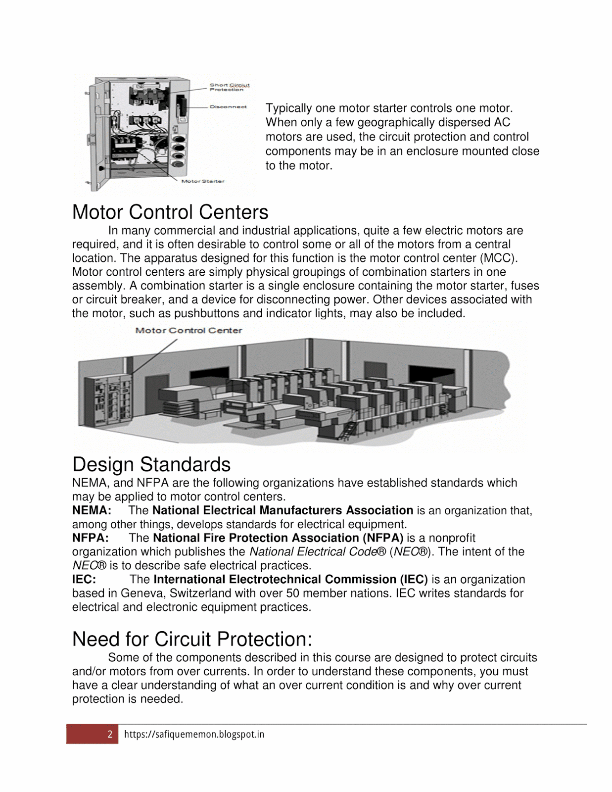
Household Power Saver

Low-energy home appliances have recently received a lot of attention from consumers and manufacturers. It is usually a small tool that should be connected to any AC sockets in the house (Especially near the Energy Meter) used in living rooms to save energy and reduce electricity bills. In addition, some companies claim to save energy by up to 40% of their energy.
Applicable Power Conservation Policy as per Performance
Power Saver is a tool that connects to a power socket. Obviously keeping the device connected will quickly reduce your power consumption. Typical savings claims are between 25% and 40%.
It is well known that the electricity that comes into our homes is not naturally stable. There are many variations, ups and downs, and surges / Spikes in this stream. The latter unstable cannot be used by any household appliances. In addition, current fluctuations waste energy from the circuit by converting electrical energy into thermal energy.
This heat energy not only damages the atmosphere, but it also damages electrical appliances and the cable circuit.

Power Saver keeps electricity inside using a capacitor system and delivers it smoothly to normal without spikes. The systems also automatically remove carbon from the circuit and promote a smooth flow of electricity. This means we will have less energy spikes. More electricity flowing around the circuit can be used to generate more electricity than before.
It is basically said that Power Savers operate on the principle of surgical protection technology. Power savers work in directing this volatile current to provide smooth and continuous output. Voltage fluctuations are unpredictable and cannot be controlled. Power savers use capacitors for this purpose. When there is an increase in power in the circuit, the energy storage capacitor retains the excess current and releases it when it suddenly drops. So only the smooth output from the device.
In addition, the energy reservoir also removes any type of carbon from the system, which facilitates more smooth flow. The main advantage of power savers is not that they provide a support system at low current times, but that they protect household items. It is well-known that the sudden rise of power can destroy electricity. Therefore, energy conservation not only protects the machine but also extends its life span. In addition, they reduce energy consumption as well as electricity bills.
The amount of energy stored by an energy reservoir depends on the amount of material used in the electrical circuit. Also, the system takes at least a week to fully adapt to the circuit, before it begins to show its high performance. High energy efficiency will be seen in areas where current volatility is very high.
To support the above statement we first need to understand three words:
1. Type of electrical load in the house,
2. Basic terminology (KW, KVA, KVAR).
3. The electricity company's electricity tax method for the home buyer and the consumer of the industry.
There are two types of load available in each house: one that can withstand lamps such as incandescent lamps, heaters etc. and other powerful or flexible ones such as ACs, refrigerators, computers, etc.
The strength factor of the Resistance Load such as a toaster or ordinary incandescent lamp is 1 (one). Devices with coils or capacitors (such as pumps, fans and ballast flashlights) - Active load has less than one power factor. If the power factor is less than 1, the current and voltage are out of phase. This is due to the energy being stored and discharged into inductors (car coil) or capacitors throughout the AC cycle (usually 50 or 60 times per second).
There are three words that need to be understood when working with alternating power (AC).
1. The First Term is a kilowatt (kW) and represents True Power. Real power can do the job. The use meters on the House side measure this value (Real Power) and the Energy Company charge for it.
2. The second term is active power, measured by KVAR. Unlike kW, it cannot do the job.Restay customers do not pay KVAR, and the meters used in homes do not record again.
3. The third term is the physical force, called KVA. By using multiple meters we can measure current and voltage and then re-read together we get the visible power in the VA.
Power triangle
Power Factor = Real Power (Watts) / Visual Energy (VA)
Therefore, Real Power (Watts) = Visual Power × PF = Voltage × Ampere × PF.
Ideally PF = 1, or cohesive, in the application describes the pure and desirable energy consumption especially for Home Appliances (dispersed output power equal to the input power used).
In the above formula we can see that when the PF is less than 1, the amperes (current usage) of the machines increase, and the opposite verse.
With AC Resistive Load, the voltage stays in the current phase and produces a positive power factor equal to 1. However, with inductive or capacitive loads, the current waveform is delayed after the voltage waveform and is not in tandem. This is due to the natural structures of these devices to store and release energy through AC wave fluctuations, and this results in a completely distorted wave, reducing the amount of PF used.
The manufacturers claim that the above problem can be solved by installing a well-calculated inductor / capacitor network and changing it automatically and appropriately to correct this variability. The energy saving unit is designed specifically for this purpose. This adjustment is able to bring the level of PF closer to unity, thereby enhancing significant power significantly. Improved optical power will mean less CURRENT use of all household appliances.
So far everything looks fine, but what about the use of the above fix?
The Utility Bill We Pay is never based on Apparent Power (KVA) but based on Real Power (KW). The service bill we pay is never about Physical Power - it is Real Power.
By Reducing Current Consumption Does Not Reduce Home Consumer Energy Debts.
Home Conservation Energy Conservation Study
Let's try to study the Effective Home Electricity Load and the Voltage Spectrum feature for example.
1. Energy Conservation in Active Home Load
Let's Take One Example of Functional Load: Refrigerator with Real Rated Power of 100 watts of 220 V AC has PF = 0.6. Thus Power = Volt X Amplifier X P.F becomes 100 = 220 × A × 0.6 Therefore, A = 0.75 Ampere
Now let's say that after installing Power Conservation when PF is brought to about 0.9, the above result will now appear as follows: 100 = 220 × A × 0.9 And A = 0.5 Ampere
In the second statement clearly shows that the current consumption reduction is refrigerant, but interesting in both cases, Real Power remains the same, i.e. the refrigerator continues to use 100 watts, so the utility bill remains the same. This only proves that although the PF-made amendment to energy conservation may reduce the Amperage of electrical equipment, it will never reduce their energy consumption and the value of the Electricity Bill.
Active power is not a problem for Functional Load of household appliances such as A.C, Freeze, motor in its operation. It is a problem for an electric company if it charges only KW. If both customers use the same amount of real power but one has a power factor of 0.5, that customer also doubles the current. This current increase requires Power Company to use larger transformers, cables and related equipment.
Reimburseing these costs The Power Company has charged Chargers to industry customers for their low power supplies and has provided them with benefits when they upgrade their Power Factor internally. Residential customers (households) are not charged extra fees for their active capacity.
2. Energy Conservation in Resistant Home Load
Since the opposing load does not carry PF so there is no problem regarding Voltage and Curent filtering, So Power = Current Voltage X.
3. In the case of Voltage Spike / Flexible Household Flexibility
In the above discussion it simply proves that as long as the voltage and current do not change, the energy used will also remain unchanged. However, if there is an increase in electrical energy due to fluctuations, as described above your electrical appliances will be forced to use the same amount of energy. This becomes even more evident because the current, which is a function of voltage, also increases equally. However, this increase in power consumption will be negligible; The following simple statistics will prove this.
Consider a bulb that consumes 100 watts of 220 volts. This means that at 240 volts it will use about 109 watts of power. The increase is almost 9% and since such fluctuations are not uncommon, this number may be reduced to less than 1%, and that is negligible.
So the above discussions prove conclusively that energy conservation will never work and this idea is impossible.
What happens if Power Storage is installed?
Fig. Shows the effect of using the Power Saver. The air conditioner (with a large compressor motor) still consumes active energy but is supplied by a nearby capacitor (which is in those boxes "KVAR"). If you were to mount it on an air conditioner and turn it on with an air conditioner and mix the capacitor size properly, there would be no active force on the return line of the fuse panel.
If the cable between the panels of your fuse is too long and too low, lowering the current may result in cooling and high voltage in the air conditioner. This saving due to cooler cables is less.

What happens when Power Storage is installed
Another problem is that when you install a "KVAR" unit on a fuse panel, it does nothing to lose heat other than two meters of large wire between the fuse panel and the usage meter. Many KVAR units are sold as boxes that you place in one place.
Conclusion
Energy efficiency equipment improves energy quality but generally does not improve energy savings (meaning it will not reduce your energy bill). There are a number of reasons why their energy-saving claims may be exaggerated.
First, residential customers are not charged KVA - hourly usage, but by kilowatt-hour. This means that any savings on energy demand will not directly lead to a reduction in the residential service bill.
Second, the only real energy saving potential would be if the product was placed only near a circuit while active loading (such as an engine) was running, and removed from the circuit when the engine was not running. This does not happen, given that there are a few engines in a typical home that can come in at any time (refrigerator, air conditioner, HVAC spray, vacuum cleaner, etc.), but the Power Store itself is designed to be permanently connected, not supervised. house breaker panel.
And certainly not in the way that manufacturers recommend installing them, that is, permanently connecting them to the main panel. Doing so drains the capacitive factor of energy when inductive motors are turned off and can cause real problems with ringing voltages.
KVAR requires full size to measure inductive loads. Since our motors rotate and close and we do not use air conditioner in winter, there is no way to measure it properly unless we have something to monitor the line and turn it on and off the capacitors as needed.
Adding a capacitor can increase the voltage of the line to dangerous levels because it interacts with incoming power lines. Adding a capacitor to a line with harmonic frequencies (created by certain electronic devices) on it can cause unwanted noise and high waves.
In commercial environments, energy efficiency adjustments are rarely less expensive based on energy efficiency alone. The bulk of the cost of adjusting the power factor that can be supplied is in the form of avoided costs of the low power element.
Energy savings are usually less than 1% and remain less than 3% of the load, the highest percentage occurs when engines are a major component of the entire facility load. Energy saving alone does not make installation costs effective.