Showing posts with label electrical engineering. Show all posts

Monday 18 April 2022

Design of Lighting Schemes

 i. Illumination Level:

This is the most vital factor because a sufficient illumination is the basic means whereby we are able to see our surroundings.

For each type of work there is a range of brightness most favourable to output i.e. which causes minimum fatigue and gives maximum output in terms of quality depends upon:

(i) The size of the objects to be seen and its distance from the observer. Greater the distance of the object from observer and smaller the size of the object, greater will be the illumination required for its proper perception and

(ii) Contrast between the object and back-ground-greater the contrast between the colour of the object and its background, greater will be the illumination required to distinguish the object properly. Objects which are seen for longer duration of time required more illumination than those for casual work. Similarly moving objects required more illumination than those for stationary objects.

ii. Uniformity of Illumination:

The human eye adjusts itself automatically to the brightness within the field of vision. If there is a lack of uniformity, pupil or iris of the eye has to adjust more frequently and thus fatigue is caused to the eye and productivity is reduced. It has been found that visual performance is best if the range of brightness within the field of vision is not greater than 3:1, which can be achieved by employing general lighting.

iii. Shadows:

In lighting installations, formation of long and hard shadows causes fatigue of eyes and therefore is considered to be a shortcoming. Complete absence of shadows altogether again does not necessarily mean an ideal condition of lighting instillations. Contrary, perhaps to popular opinion, a certain amount of shadow is desirable in artificial lighting as it helps to give shape to the solid objects and makes them easily recognised.

iv. Glare:

It may be direct or reflected i.e. it may come direct from the light source or it may be reflected brightness such as from a desk top, nickeled machine parts, or calendared paper.

Direct glare from a source of light is more common, and is more often a hindrance to vision. A glance at the sun proves that an extremely bright light source causes acute eye discomfort. Reflected glare is glare which comes to the eyes as glint or reflection of the light source in some polished surface.

v. Mounting Height:

In case of direct lighting it depends upon the type of building and type of lighting scheme employed. For rooms of large floor area, the luminaries should be mounted close to ceiling as possible. In case of indirect and semi-indirect lighting, it would be desirable to suspend luminaries enough down from ceiling to give uniform illumination.

vi. Spacing of Luminaries:

The distance of light source from the wall should be equal to one half the distances between two adjacent light sources. The distance between light fittings should not exceed 1.5 times the mounting height.

Different lighting schemes

 Different lighting schemes may be classfied as:

(i) direct lighting, (ii) indirect lighting, (iii) semi-direct lighting, (iv) semi-indirect lighting, and (v) general diffusing systems.
Lighting


(i) Direct Lighting
As the name indicates, in the form of lighting, the light from the source falls directly on the object or the surface to be illuminated. It is most commonly used type of lighting scheme. In this lighting scheme more than 90 percent of total light flux is made to fall directly on the working plane with the help of deep reflectors. Though it is most efficient but causes hard shadows and glare. It is mainly used for industrial and general out-door lighting.

direct lighting

(ii) Indirect Lighting

In this light scheme more than 90 percent of total light flux is thrown upwards to the ceiling for diffuse re­flection by using inverted or bowl reflectors. In such a system the ceiling acts as the light source, and the glare is reduced to mini­mum. The resulting illumination is softer and more diffused, the shadows are less prominent and the appearance of the room is much improved over that which results from direct lighting. It is used for decoration purposes in cinemas theatres and hotels etc. and in workshops where large machines and other obstructions would cause trouble some shadows of direct lighting is employed.


Indirect Lighting

(iii) Semi-direct System

In this lighting scheme 60 to 90 percent of the total light flux is made to fall downwards directly with the help of semi-direct reflectors, remaining light is used to illuminate the ceiling and walls. Such a lighting system is best suited to rooms with high ceilings where a high level of uniformally distributed illumination is desirable. Glare in such units is avoided by employing diffusing globed which not only improve the brightness towards the eye but improve the efficiency of the systems with reference to working place.


Semi-Direct Lighting

(iv) Semi-indirect Lighting

In this lighting scheme 60 to 90 percent of total light flux is thrown upwards to the ceiling for diffuse reflection and the rest reaches the working plane directly except for some absorption by the bowl. This lighting scheme is with soft shadows and glare free. It is mainly used for indoor light decoration purposes.


Semi-Indirect Lighting

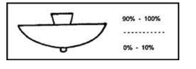
(v) General Diffusing System
In this system, luminaries are employed which have almost equal light distribution downwards and upwards.


Saturday 16 April 2022

ADVANTAGES OF PER UNIT SYSTEM


PER UNIT SYSTEM

The per-unit system expressed the voltages, currents, powers, impedances, and other electrical quantities basis by the equation:

Quantity per unit (pu) = Actual value/ Base value of quantity

ADVANTAGES OF PER UNIT SYSTEM

  1. While performing calculations, referring quantities from one side of the transformer to the other side serious errors may be committed. This can be avoided by using per unit system.
  2. Per unit impedances of electrical equipment of similar type usually lie within a narrow range, when the equipment ratings are used as base values.
  3. Manufacturers usually specify the impedances of machines and transformers in per unit or percent of name plate ratings.
  4. Transformers can be replaced by their equivalent series impedances.
  5. Reduced calculations in three-phase systems.
  6. For apparatus of the same general type the p.u. and volt drops or losses are in the same order, regardless of size.

PER UNIT CONVERSION PROCEDURE OF SINGLE PHASE

  1. Pick a VA base for the entire system, Sbase
  2. Pick a voltage base for each different voltage level, Vbase.
  3. Voltage bases are related by transformer turns ratios.
  4. Voltages are line to neutral.
  5. Calculate the impedance base, Zbase = (Vbase)2/Sbase
  6. Calculate the current base, Ibase =Vbase/Zbase
  7. Convert actual values to per unit
  8. Convert to per unit (p.u.) (many problems are already in per unit)
  9. Solve
  10. Convert back to actual as necessary

Wednesday 16 March 2022

EHVAC Vs HVDC TRANSMISSION


EHVAC Vs HVDC TRANSMISSION

HVDC vs HVAC Transmission Systems

HVDC stands for High Voltage Direct Current while HVAC stands for High Voltage Alternating Current. These are typically the rate of voltage, either DC (HVDC) or AC (HVAC) that are employed for energy transmission over long distances. HVDC is preferred to be utilized for transmitting energy over long distances, commonly more than 375 miles.

HVDC vs HVAC Transmission Systems (Reference: tdworld.com)

Nowadays, both formats of power transmission are employed all over the world. While these both have some advantages and disadvantages, we will explain each of them briefly in this post below based on different characteristics to discuss the HVDC vs HVAC transmission systems fundamentally.

Cost of Transmission

We understand that energy transmission over long-distance application needs high voltages. The power is used in terminal stations that modify the voltage rates. So, the total price of transmission is based on the cost of the transmission line and the terminal source’s situation.

Terminal Station

The great number of voltages transmitted within electrical terminal sources and their operation are introduced as the voltage conversion. The system employed for voltage conversion at these sources is mainly transformers in the case of AC types that is converted between low and high Voltages. Whereas in the case of DC type, the terminal sources utilize IGBTs or thyristor-based converters for modification between low and high DC voltage.

Since the transformers are less expensive and more reliable than these solid-state converters, the AC terminal sources are cheaper than DC types. Thus, the voltage modification in AC is less costly than DC forms.

Transmission Line

The transmission line price is based on the number of conductors being employed and the price of the transmission tower.

In the aspect of conductors being employed for transmission systems, the HVDC transmission type needs just two conductors, while the HVAC transmission form needs 3 or more than 3 instruments (including the covered conductor according to the harmful effects).

Because of the massive mechanical load on AC tower systems, their operation requires to be stronger and it should be taller and wider than HVDC transmission systems. The transmission line price rises with the distance and it is far higher than the HVDC line per 60 miles of a transmission path.


Overall Cost of Transmission

The overall cost of transmission is based on the terminal price (remains fixed) and the line price (rises with distance). As a result, the overall cost of the transmission system increases with distance.

HVDC vs HVAC Transmission Systems Cost (Reference: electricaltechnology.org)

The transmission path at which the total investment cost for HVAC begins to increase is introduced as Break-even Distance. This value is evaluated around 400 – 500 miles. HVDC is a more suitable option for energy transmission in the break-even distance. Although, below this distance, HVAC is more effective than HVDC. This data can be simply understood by the previous diagram.

Flexibility

Because the HVDC transmission is employed for transmission over long-distance applications between two areas, we cannot extract power at any section in-between since it would require an expensive converter to reduce such high DC voltages. In contrast, the HVAC transmission provides flexibility using a simple and cheap device like transformers at several terminal stations to control these high voltages.

Power Losses

The HVAC power transmission format has more power wastes such as Radiation losses, Induction losses, Skin effect, Corona losses, etc.

The radiation & induction losses depend on the magnetic field variation near the HVAC conductor. A massive conductor starts operating as an antenna and radiates some power that cannot recover, while the induction wastes are the energy loss when the current is produced in close conductors based on the continuously magnetic field variation. Since DC has an identical magnetic field, the HVDC type is free from these losses.

The alternating current produced in a conductor is separated in such a method that the current density wants to compose largest at the top of the conductor and minimum at the middle; this is known as the skin effect. Because much of the cross-sectional surface is ineffective and we understand that the resistance is straightly related to the cross-sectional surface, the resistance value of the conductor rises. The DC in the system is uniformly spread because the skin effect is just based on the frequency. So, only HVAC type experience power waste according to the skin effect in this aspect of HVDC vs HVAC transmission systems.

When the voltage rises more than a specific limit, the air close to the conductor begins the ionizing process and produces sparks that lose some power; this is introduced as corona discharge. The losses of corona discharge are also based on the frequency and because DC systems have zero frequency, the corona waste in HVAC is almost 3 times higher than that in HVDC.

The Skin Effect in Detail

The skin effect forces the conductor to keep most of the current at its top and less current at the center. It is based on the frequency and directly proportional to it. It reduces the efficiency of the conductors being employed. Thus, in order to provide a larger current, the cross-sectional section of the conductor requires to be increased.

Skin Effect in HVDC vs HVAC Transmission Systems (Reference: electricaleasy.com)

So, the HVAC requires a larger diameter device to carry the equal value of current as compared to the HVDC type employing a shorter diameter conductor.

Current & Voltage Ratings of Cable

As we discussed before, the current and voltage ratings of a cable are the optimum allowable range that it can be passed. The AC systems have a peak current and voltage that is practically 1.4 times greater than its average (the average practical energy delivered) or its DC norm. But in DC type, the average and peak values are equal.


Peak and Average Values for Transmission Systems (Reference: electrical4u.com)

The conductor should be evaluated for the peak voltage and current for the HVAC type which loses almost 30% of its ideal capacity in comparison with HVDC form, which uses the complete capacity of the conductor. So, a conductor with an identical size can be more preferred in HVDC vs HVAC transmission systems.

Right-of-Way

The right of way is the right method to use the land to and from another section of land. In the exploration of HVDC type, it includes a narrower right-of-way since it can employ smaller kinds of towers with fewer conductors being applied, i.e., two in DC types and 3 in 3-phase AC systems. Also, the insulators used in the main towers should be rated for peak voltages in AC systems.

The right-of-way influences the prices of substances used and fabrication requirements for the different transmission systems. We can conclude that HVDC types have a narrower right-of-way than HVAC transmission systems.

Submarine Power Transmission

We use cables in order to move power offshores employing submarine power transmission. At the same time, the cables provide certain capacitance generated between two conductors that operate in parallel arrangement to transmit power over long-distance applications.

The capacitance value is just based on the variation in voltage which is continuously happening in AC types, and only during switching mode in DC systems. The cable does not provide energy due to such capacitance (at the receiving section) before being completely charged. The cable is discharged and charged continuously in alternating current (50 or 60 times per second) which forces the system to lose a huge power. In contrast, the cable is charged only once in DC type. As a result, the submarine power system employed HVDC for energy transmission.

Controllability of Power Flow

When we discuss the HVDC vs HVAC transmission systems in the case of controllability, HVDC form uses particular converters of IGBT semiconductors which can be switched off and on several times in a period and control the total system, while HVAC has not a controllable part for Power flow. While the converters used in HVDC are complex, they help in controlling the distribution of energy to the entire setup and also increase the harmonic performance. These developed electronic converters provide fast protection against line errors and fault clearance contrary to the HVAC types.

Circuit Breaker

The Circuit breaker is a highly important section of power transmission systems. It can cease the whole circuit operation for reaction to any fault or maintenance. The circuit breaker requires arc-extinguish abilities in the current to stop the power supply.

The direction and value of the current modify continuously in HVAC systems and the arc is typically extinguished based on the presence of several zero currents in a second that present various chances to stop the arc. Whereas in DC form, the current is fixed and there are no zero currents, so artificial zero currents should be produced employing particular circuitry to stop the arc.

As a result, in the comparison of HVDC vs HVAC transmission systems, the circuit breakers for HVAC are easy to modeling according to the “self-arc-extinguish” feature. This is while for HVDC, the circuit-breaker modeling is relatively complex and they are more costly than HVAC types.

Generating Interference

The AC systems produce a magnetic field with continuously variable values that can cause interference with the conductors in the nearby communication. Because DC types have a constant magnetic field, they do not cause such problems.

Key Differences to Contrast Hvdc vs Hvac Transmission Systems

At what follows, key differences between HVDC vs HVAC transmission systems are summarized:

  • Skin effect is zero in DC systems. Also, corona wastes are especially lower in DC type. An HVDC path has noticeably lower wastes in comparison with HVAC over long-distance applications.
  • HVDC transmission path would cost lower than an HVAC type.
  • Based on the absence of inductance value in DC type, an HVDC path provides better voltage monitoring. Also, HVDC supplies greater controllability in comparison with HVAC.
  • AC power grids are normalized for 60 Hz in some regions and 50 Hz in others. It is impractical to combine two power grids operating at different frequencies using an AC junction. An HVDC port makes this possible for power grids.
  • Interference with close relative lines is lower in HVDC types than an HVAC overhead line.
  • The short circuit current rate in the receiving setup is great in longer distance HVAC transmission system. An HVDC type does not chip in such circuit current of the AC form.


Conclusion

In a general comparison for HVDC vs HVAC transmission systems, HVDC transmission types have many more benefits over HVAC types, including controllability, stability, etc. HVDC systems are more cost-effective for distances greater than the break-even point. Submarine HVDC instruments can be more reliable for use in offshore wind farms as they are less expensive than undersea HVAC wires. As a result, there is an increasing tendency to choose the HVDC transmission type. However, HVAC systems are also employed because they have their particular advantages in distribution and transmission, such as they can be simply stepped down and stepped up which is an important matter in certain applications. HVDC is practically a supplement for AC forms rather than an opponent.


Monday 14 March 2022

Smart Grids

     A Smart Grid is an electricity Network based on Digital Technology that is used to supply electricity to consumers via Two-Way Digital Communication. This system allows for monitoring, analysis, control and communication within the supply chain to help improve efficiency, reduce the energy consumption and cost and maximize the transparency and reliability of the energy supply chain.

    Smart grid is a large ‘System of Systems’, where each functional domain consists of three layers: 

(i) the power and energy layer, 

(ii) the communication layer, and 

(iii) the IT/computer layer.

     Layers (ii) and (iii) above are the enabling infrastructure that makes the existing power and energy infrastructure ‘smarter’.

It uses smart meters and appliances, renewable and efficient energy resources.

  • The system delivers electricity via 2-way digital communication. It allows consumers to interact with the grid.
  •  It reduces energy consumption and reduces cost to the consumers by smart means. Electric supply companies make efficient usage of energy and consecutively will be able to meet the varying load demands of the consumers.
Features of Smart Grid
    Smart grid has several positive features that give direct benefit to consumers:
  • Real time monitoring.
  • Automated outage management and faster restoration.
  • Dynamic pricing mechanisms.
  • Incentivize consumers to alter usage during different times of day based on pricing signals.
  • Better energy management.
  • In-house displays.
  • Web portals and mobile apps.
  • Track and manage energy usage.
  • Opportunities to reduce and conserve electricity etc.
  • Benefits of Smart Grid Deployments

  • Peak load management, improved QoS and reliability.
  • Reduction in power purchase cost.
  • Better asset management.
  • Increased grid visibility and self-healing grids.
  • Renewable integration and accessibility to electricity.
  • Satisfied customers and financially sound utilities etc.

Smart Grid Architecture Components


The figure depicts generic Smart Grid Network Architecture components or modules with different reference points. As shown typical smart grid network consists of following components.
• Grid domain (Operations include bulk generation, distribution, transmission)
• Smart meters
• Consumer domain (HAN (Home Area Network) consists of smart appliances and more)
• Communication network (Connects smart meters with consumers and electricity company for energy monitoring and control operations, include various wireless technologies such as zigbee, wifi, HomePlug, cellular (GSM, GPRS, 3G, 4G-LTE) etc.
• Third party Service providers (system vendors, operators, web companies etc.)


Thursday 16 December 2021

How to Find The Suitable Size of Cable & Wire for Electrical Wiring Installation? With Examples

  •     

How to Find The Suitable Size of Cable & Wire for Electrical Wiring Installation? With Examples

Remember that it's far very crucial to choose proper wire size while sizing a wire for electrical installations. An inappropriate size of wire for heavy loads current can also create chaos which results in failure of the electrical system, hazardous fire and serious injuries.

Voltage Drop in Cables

Whenever the current flows through the conductor, there will be a voltage drops in that conductor. Normally, voltage drop may be neglected for small length of conductors but in case of a lower diameter and long length conductors we should consider a significant voltage drops for proper wiring installation and future load management.

According to Institute of Electrical and Electronics Engineers (IEEE) rule B-23, at any point between a power supply terminal and installation, voltage drop should not increase above 2.5% of provided (supply) voltage 


Example:

Let us assume , the supply voltage is 230V AC, then the value of permissible voltage drop should be;

  • Permissible Voltage Drop = 230 x (2.5/100) = 5.75V

Similarly, if the supply voltage is 110V AC, the Permissible Voltage Drop  should be not more than 2.75V ( 110V x 2.5%).

In electrical wiring circuits, for sub circuits the value of voltage drop should be half of that permissible voltage drop.

Normally, the voltage drop is expressed in Ampere per meter (A / m)

Tables & Charts for Proper Cable & Wire Sizes

Below are the important tables which you should follow for determining the proper size of cable for Electrical Wiring Installation


How to calculate Voltage Drop in a Cable?

Step no. 1:         Calculate the maximum allowable  voltage drop.

Step no. 2:          Calculate the load current

Step no. 3:          After finding the load current select a proper cable from table 1

Step no. 4:          from table 1 find the voltage drop of the cable and multiply with the length of cable

Step no. 5:          Now multiply this calculated value of volt drop by load factor where;

Load factor = Load Current to be taken by Cable/ Rated Current of Cable given in the table.

                          This is the value of Volt drop in the cables when load current flows through it.

Step no. 6:          If the calculated value of voltage drop is less than the value calculated in step (1)                                   (Maximum allowable voltage drop), than the size of selected cable is proper

Step no. 7:          If the calculated value of voltage drop is greater than the value calculated in step (1)                               (Maximum allowable voltage drop), than calculate voltage drop for the next (greater in                             size) cable and so on until the calculated value of voltage drop became less than the                                 maximum allowable voltage drop calculated in step (1).


Example :

For Electrical wiring in a building, Total load is 5kW and the length of the cable from Main panel to sub circuit is 40 feet. Supply voltages is  230V and temperature is 40°C. Find the suitable size of cable which is going through conduits .

Solution:-

    Ø Total Load = 5kW

Ø                           Let us assume at max 20% overload occurs i.e. 1.2*5kW=6kW or 6000W

Now for 6000W load current will flow i.e. 6000/230= 26.08A

ØNow we have to select the size of cable from table 1 for 26.08A current which is 7/0.036 (28                      Amperes). It means we can use 7/0.036 cable according to table 1.

Ø                         Now check the selected (7/0.036) cable with temperature factor in Table 3, so the temperature                factor is 0.94 (in table 3) at 40°C  and current carrying capacity of (7/0.036) is 28A, therefore,                current carrying capacity of this cable at 40°C (104°F) would be

Current rating for 40°C  = 28 x 0.94 = 26.32 Amp.

                  Maximum current carrying capacity is 26.32 A and actual is 26.08A.Hence   this size of cable                  (7/0.036) is also suitable.

Ø                          Now find the voltage drop for 100 feet for this (7/0.036) cable is 7V, But in our case, the length of cable                 is 40 feet. Therefore, the voltage drop for 40 feet cable would be;

                Actual Voltage drop for 40 feet = (7 x 40/100) x (26.08/28) = 2.608V

                And Allowable voltage drop = (2.5 x 220)/100 = 5.5V

             Here The Actual Voltage Drop (2.608V) is less than that of maximum allowable voltage drop of 5.5V.                  Therefore, the most suitable cable size is (7/0.036) for that given load.


Thursday 26 July 2018

Why Capacitors bank is connected parallel with a load to improve power factor

we can improve the power factor by connecting the capacitor bank in parallel or series.If we connect the capacitor bank in parallel that means additional installation and O&M costs can be saved. In fact when we connect the capacitor bank to the series there is a decrease in the power of those capacitors in the series, a distance between 10-20% of the minimum transmission voltage. So power outages are not a major issue. The real problem is protection and the resulting cost: in the event of a short-circuit fault in the load there is a chance that all the transmission voltage will be applied to those capacitors and may fail. As we know it can be protected from over voltage voltages by using appropriate switch switches and split gap sparks. It therefore means additional installation and O&M (operation and maintenance) costs that can be avoided simply by connecting the capacitors accordingly.
Another great advantage is that when we connect it seamlessly you separate your installation, which makes it easier to repair. For example, if you need to replace some bank capacitors, or add others, to the corresponding series you need to do to disconnect the bank throughout the network, instead of the whole facility if you were connected to a network. series.
Just for the record, there are cases where capacitors are connected in series, but not in the load terminals and do not affect the compensating capacitor banks that are active (well, not really). These are the conditions in which it is desired to increase the natural strength of the transmission line. They are also connected to the series to minimize the reaction of the long line (not to be confused with its feature). Therefore, increasing its current capacity and consequently increasing its capacity and stability.This measure is mainly used for long transmission lines, i.e. 500 km and more.

Monday 11 September 2017

TRANSFORMER MAINTENANCE GUIDELINES

TRANSFORMER MAINTENANCE GUIDELINES
Following specific checking and maintenance guidelines as well as conducting routine inspections will help ensure the prolonged life and increased reliability of a transformer. The frequency of periodic checks will depend on the degree of atmospheric contamination and the type of load applied to the transformer.
Routine checks and resultant maintenance
Sl No
Inspection Frequency
Items to be inspected
Inspection Notes
Action required if inspection shows unsatisfactory conditions
1.1
Hourly
Ambient Temperature
-
-
1.2
Hourly
Oil & Winding Temperature
Check that temperature rise is reasonable
Shutdown the transformer and investigate if either is persistently higher than normal
1.3
Hourly
Load (Amperes) and Voltage
Check against rated figures
Shutdown the transformer and investigate if either is persistently higher than normal
2.1
Daily
Oil level in transformer
Check against transformer oil level
If low, top up with dry oil examine transformer for leaks
2.2
Daily
Oil level in bushing


2.3
Daily
Relief diaphragm

Relief diaphragm
3.1
Quarterly
Bushing
Examine for cracks and dirt deposits
Clean or replace
3.2
Quarterly
Oil in transformer
Check for dielectric strength & water content
Take suitable action
3.3
Quarterly
Cooler fan bearings, motors and operating mechanisms,
Lubricate bearings, check gear boxes, examine contacts
Replace burnt or worn contact or other parts

4.1

Yearly
Oil in transformer
Check for acidity and sludge
Filter or replace
4.2
Yearly
Oil filled bushing
Test oil
Filter or replace
4.3
Yearly
Gasket Joints
-
Tighten the bolts evenly to avoib uneven pressure
4.4
Yearly
Cable
boxes Check for sealing arrangements for filling holes.
Replace gasket, if leaking
4.5
Yearly
Surge Diverter and gaps
Examine for cracks and dirt deposits
Clean or replace
4.6
Yearly
Relays, alarms & control circuits
Examine relays and alarm contacts, their operation, fuses etc. Test relays
Clean the components and replace contacts & fuses, if required.
4.7
Yearly
Earth resistance

Take suitable action, if earth resistance is high
IR testing:
The transformer should be de-energized and electrically isolated with all terminals of each
winding shorted together. The windings not being tested should be grounded. The meg-ohmmeter
should be applied between each winding and ground (high voltage to ground and low voltage to
ground) and between each set of windings (high voltage to low voltage). The meg-ohm values
along with the description of the instrument, voltage level, humidity, and temperature should be
recorded for future reference.
The minimum megaohm value for a winding should be 200 times the rated voltage of the winding
divided by 1000. For example, a winding rated at 13.2kV would have a minimum acceptable value
of 2640 megaohms ([13,200V x 200] / 1000). If previously recorded readings taken under similar
conditions are more than 50% higher, the transformer should be thoroughly inspected, with
acceptance tests performed before reenergizing.
Turns ratio testing:
 The transformer turn ratio is the number of turns in the high voltage winding divided by the
number of turns in the low voltage winding. This ratio is also equal to the rated phase voltage of
the high voltage winding being measured divided by the rated phase voltage of the low voltage
winding being measured.
Transformer turns ratio measurements are best made with specialized instruments that include
detailed connection and operating instructions. The measured turns ratio should be within 0.5% of
the calculated turns ratio. Ratios outside this limit may be the result of winding damage, which has
shorted or opened some winding turns.
Insulation PF testing:
Insulation PF is the ratio of the power dissipated in the resistive component of the insulation
system, when tested under an applied AC voltage, divided by the total AC power dissipated. A
44
perfect insulation would have no resistive current and the PF would be zero. As insulation PF
increases, the concern for the integrity of the insulation does also. The PF of insulation systems of
different vintages and manufacturers of transformers varies over a wide range (from under 1% to
as high as 20%). As such, it's important that you establish a historic record for each transformer
and use good judgment in analyzing the data for significant variations.
Acceptance testing
Acceptance tests are those tests made at the time of installation of the unit or following a service
interruption to demonstrate the serviceability of the transformer. This testing also applies to drytype
units. The acceptance tests should include IR testing, insulation PF measurement, and turns
ratio testing, all as described under periodic tests. In addition, winding resistance measurements
should be made and excitation current testing done.
Winding resistance measurement:
Accurate measurement of the resistance between winding terminals can give an indication of
winding damage, which can cause changes to some or all of the winding conductors. Such
damage might result from a transient winding fault that cleared; localized overheating that opened
some of the strands of a multi-strand winding conductor; or short circuiting of some of the winding
conductors.
Sometimes, conductor strands will burn open like a fuse, decreasing the conductor cross section
and resulting in an increase in resistance. Occasionally, there may be turn-to-turn shorts causing
a current bypass in part of the winding; this usually results in a decrease of resistance.
To conduct this test, the transformer is de-energized and disconnected from all external circuit
connections. A sensitive bridge or micro-ohmmeter capable of measuring in the micro-ohm range
(for the secondary winding) and up to 20 ohms (for the primary winding) must be used. These
values may be compared with original test data corrected for temperature variations between the
factory values and the field measurement or they may be compared with prior maintenance
measurements. On any single test, the measured values for each phase on a 3-phase
transformer should be within 5% of the other phases.
Excitation current measurement:
The excitation current is the amperage drawn by each primary coil, with a voltage applied to the
input terminals of the primary and the secondary or output terminals open-circuited. For this test,
the transformer is disconnected from all external circuit connections. With most transformers, the
reduced voltage applied to the primary winding coils may be from a single-phase 120V supply.
The voltage should be applied to each phase in succession, with the applied voltage and current
measured and recorded.
If there is a defect in the winding, or in the magnetic circuit that is circulating a fault current, there
will be a noticeable increase in the excitation current. There is normally a difference between the
excitation current in the primary coil on the center leg compared to that in the primary coils on the
other legs; thus, it's preferable to have established benchmark readings for comparison.
Variation in current versus prior readings should not exceed 5%. On any single test, the current
and voltage readings of the primary windings for each of the phases should be within 15% of each
other.
Applied voltage testing:
 The applied voltage test is more commonly referred to as the "hi-pot test." This test is performed
by connecting all terminals of each individual winding together and applying a voltage between
windings as well as from each winding to ground, in separate tests. Untested windings are
grounded during each application of voltage.
This test should be used with caution as it can cause insulation failure. It should be regarded as a
proof test to be conducted when there has been an event or pattern in the transformer's operating
history that makes its insulation integrity suspect.
45
DC applied voltage tests are often conducted in the field because DC test sets are smaller and
more readily available than AC applied voltage sets. With DC tests, the leakage current can be
measured and is often taken as a quantitative measure. However, DC leakage current can vary
considerably from test to test because of creepage across the complex surfaces between
windings and between windings and ground.
The use of AC voltage is preferable since the transformer insulation structures were designed,
constructed, and tested with the application of AC voltage intended.
Impedance testing:
An impedance test may be useful in evaluating the condition of transformer windings, specifically
for detecting mechanical damage following rough shipment or a service fault on the output side
that caused high fault currents to flow through the transformer windings. Mechanical distortion of
the windings will cause a change in their impedance. To maximize the effectiveness of this test, a
measurement should be taken during the transformer's initial installation to establish a benchmark
value.
An impedance test is performed by electrically connecting the secondary terminals together with aconductor capable of carrying at least 10% of the line current and applying a reduced voltage to
the primary windings. This is easily accomplished by applying a single-phase voltage to each
phase in succession. The applied voltage is measured at the primary terminals and the current
measured in each line.
These values shall be recorded and then calculate the ratio of voltage to current for each phase.
This ratio should be within 2% for each phase and should not vary more than 2% between tests.
A variation of more than 2% indicates the possibility of mechanical distortion of the winding

conductors, which should be investigated as soon as possible.

Types of source

  Ideal Voltage Source:  An ideal voltage source is capable to maintain the constant voltage across its terminals. The voltage across the vo...

Translate