Wednesday, 12 April 2023

Types of source


Ideal Voltage Source: 

An ideal voltage source is capable to maintain the constant voltage across its terminals. The voltage across the voltage source terminals remains constant and the voltage is independent of the current.  An ideal voltage source must have zero internal resistance. Hence, the voltage across the load will be equal to the voltage across the terminals of the voltage source. 

The fig. 1(a) shows voltage source and 1(b) shows its output characteristic


Practical Voltage Source: 

Voltage Sources having some amount of internal resistances connecting in series is known as Practical Voltage Source. Due to this internal resistance; voltage drop takes place, and it causes the terminal voltage to reduce. The smaller is the internal resistance (r) of a voltage source, the more closer it is to an Ideal Source.


Ideal Current Source

An ideal current source that is capable of providing a constant current output regardless of the load resistance.  An ideal current source is a circuit element that maintains a prescribed current through its terminals regardless of the voltage across those terminals.

  • It produces a constant current value irrespective of the voltage across it.
  • i.e., i=is for all V

currentsource_vi

 Practical current source

A practical current source is represented as an ideal current source connected with resistance in parallel.
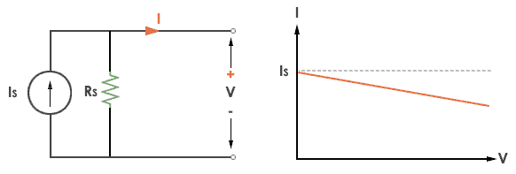
Practical Current source

The graph represents the current of the current source with respect to time. It is not constant but it also keeps on decreasing as the time passes.

A practical current source is represented as an ideal current source connected with resistance in parallel.

Practical Current source

The graph represents the current of the current source with respect to time. It is not constant but it also keeps on decreasing.


Tuesday, 11 April 2023

electric circuit and ohm law

Electric Circuit

(i)EMF: Electromotive force (emf) is the force that causes an electric current to flow in an electric

circuit.The S.I. Unit of EMF is volt (V).

(ii) Potential difference: Potential difference between two points in an electric circuit is that difference in their electrical state which ends to cause flow of electric current between them.

The S.I. unit of potential difference is volt (V)

(iii) Electric Current: The electric current is defined as the rate of flow of electric charge or electrons,

Its  S. I. unit is Ampere (A).

 (iv) Electric Power: The rate at which work is done in an electric circuit is known as electric power.

  i.e. Electrical power=  


                                                                   Power = voltage x current

P=VI

P = I2R

P = V2/ R

The basic unit of electric power is watt.

One Watt: The power in electric circuit is one watt if a electric potential of 1 volt causes 1 ampere electric current to flow through the circuit.

(v) Electrical Energy: The total amount of work done in an electric circuit is called electrical energy. Electrical Energy = Voltage x Current x time

The unit of electric energy is watt-second

Ohm’s Law 

Ohm's law states that "The potential difference between the two ends of a conductor is directly proportional to the current flowing through it, provided it's temperature and other physical parameters remains unchanged".


 That is, V α I  

V=RI 

where, R is the resistance between these two points.

Voltage= Current× Resistance
V= I×R
V= voltage, I= current and  R= resistance

The SI unit of resistance is ohms and is denoted by Ω

Limitations: Resistance, Temperature, Physical condition should remain constant.


TRANSISTORS

TRANSISTORS A transistor is a semiconductor device that contains three regions separated by two distinct PN junctions. The two junctions are...

Translate