Monday, 12 September 2022

ELECTRICAL LOAD ASSESSMENT


ELECTRICAL LOAD ASSESSMENT


Ø  Connected Load :- The sum of continues rating of all  electrical equipment connected to the supply system is known as connected load. 

Ø  Maximum Demand :- Maximum demand is the Maximum load which a consumer uses at any time which consume for min  30 mints). It is the maximum demand which determines the size and cost of the installation.

Ø  Demand Factors:- The ratio of maximum demand to the connected load is called the demand factor. It is always less than unity.

Ø  Load Factor:- The ratio of the average load to maximum load during 24 hours is called as load factor.


The load factor can  also be defined as the ratio of energy consume during a period to the energy which would have been used if the maximum demand had been maintain throughout that period.

Ø  Diversity Factor: - The ratio of the sum of  individual maximum demands to the simultaneous maximum demand on the power station is known as diversity factor.  It is always greater than unity.


Ø  Utilization Factor :- It is the measure of utility of power plant capacity and is the ratio of maximum demand to the rated capacity of power plant

Ø  Power Factor:- The POWER FACTOR is a number (represented as a decimal or a percentage) that represents the portion of the apparent power dissipated in a circuit.

 Note:

                               I.            Diversity Factor is higher, the energy is cheaper

                            II.            Load Factor, Diversity factor higher the energy per unit cost is less.

                         III.            Diversity Factor has direct effect on the fixed cost of unit generated.

Different Types of Load:-

The different types of loads are as follows

1.      Residential or domestics load

2.      Commercial load

3.      Industrial load

4.      Government load

5.      Municipal load

6.      Irrigation load


1.      Residential or domestics load:- Domestics load mainly consists of lights,fans, domestics appliances such as heaters,refrigerators,air-conditioners for rooms, radio receivers,television,LCD,LED,electric cookers, electric water-heater, single phase I.M. for pumping.

      The diversity factor of such load is between 1.2 to 1.3. The load factor of such load is very poor and it is between 10% - 20% .  

2.      Commercial load:- This type of load mainly consist of lighting for shops, advertisement ,fans and electrical appliances use for commercial purpose likes shops ,restaurants, market places etc.

      The demand factor for such load is 100% & the diversity factor is between 1.1-1.2 .The load factor of such load is between 25%- 30%.

3.      Industrial  load:- This type of load can be subdivided into sections depending on the power range required

                                           I.            Cottage industries which requires about 5kw

                                        II.            Small scale industries about 25 kw

                                     III.            Medium scale industries which requires about 25-100 kw

                                     IV.            Large scale industries which requires about 100-500 kw

                                        V.            Heavy scale industries which requires more  than 500 kw

      For large scale industries the demand factor may be taken as 70-80% and the load factor between 60-65%.

      For heavy industries the demand factor is 85- 90% and the load factor is about 70-80%

4.      Government load:- This may be classified as separate type of load when it has separate feeders & special working condition for example Defense load.

5.      Municipal Load:- Street light is one of the municipal load. This type of load is practically constant throughout the hours of darkness so the demand factor is 100%, the diversity factor can be taken as 1 when considered for the duration of street lighting load and load factor is 25-30%.

6.      Irrigation load:- This type of load is required for supplying water for fields for crops in different seasons . The demand factor 90-100%,Diversity Factor 1-1.5 and load factor 20-25% for irrigation load.

TARIFF:-

The electrical energy produced at the generating station is delivered to a large number of consumers. The rate at which energy is sold to the consumers (called tariff) is fixed by the supplying company .While fixing the tariff, the supply companies are to ensure that they should not only recover the total cost of producing the energy but also earn some profit. However, the profit should be minimum possible so that electrical energy can be sold at reasonable rates and the consumers insured to use more electricity. 

The rate of electrical energy at which it is sold to the consumers is called tariff .The supply companies invest money to generate, transmit and distribution of electrical energy,a tariff is fixed. The cost of generation depends upon the magnitude of energy consumed by the consumers and his load conditions. Therefore, due consideration is given to different types of consumers (e.g. domestic, commercial and industrial) while fixing a tariff

The main objective of the tariff is to ensure the recovery of the total cost of generation and distribution .Tariff should include the following items:

(1) Recovery of cost of electrical energy generated at the generating system.

(2) Recovery of cost on the capital investment in transmission and distribution system.

(3) Recovery of cost of operation, supplies and maintenance of equipment.

(4) Recovery of cost of metering equipment, billing and miscellaneous services .

(5) A marginal return (Profit) on the capital investment

TYPES OF TARIFF

There are various types of consumers ( domestic, commercial and industrial etc.) and their energy requirements are also different. Accordingly, several types of tariffs have been designed so far, out of which the most commonly applied are described below:

1.      SIMPLE TARIFF

2.      FLAT RATE TARRIF

3.      BLOCK RATE TARIFF

4.      TWO-PART TARIFF

5.      MAXIMUM DEMAND TARIFF

6.      POWER FACTOR TARIFF

1.Simple Tariff: The tariff in which the rate per unit of energy is fixed, is called simple tariff.

This is a simplest possible tariff. The rate per unit of energy consumed by the consumer is fixed irrespective to the quantity of energy consumed by a consumer. This energy consumed is measured by installing an energy meter

The following are the advantages :

            1.         It is in simplest form and easily understood by the consumers.

            2.         Consumer is to pay as per his consumption.

Disadvantages

1.                  Consumer is to pay the same rate per unit of energy consumed irrespective of the number of units consumed by him. Hence, consumers are not encourage to consume more energy.

2.                  The cost of energy per unit delivered is high.

3.                  The supplier does not get any return for the connection given to the consumer if consumer does not consume any energy in a particular month.

Application :

Since it is very simple form of tariff, it is generally applied to tube wells which are operated for irrigation purposes

2. Flat rate tariff.  The tariff in which different types of consumers are charged at different per unit rates is called flat rate tariff. This type of tariff is similar to simple tariff. Only difference is that consumers are grouped into different classes and each class of consumer is charged at a different per unit rate. For example flat rate for fan and light loads is slightly higher than that for power loads.

Advantages

(1) It is fairer to different types of consumers.

( 2) It is quite simple in calculations.

Disadvantages

(1) Consumers are not encouraged to consume more energy because same rate per unit of energy consumed is charged irrespective of the quantity of energy consumed.

(2) Separate meters are required to measured energy consumed for light loads and power loads.

(3) The suppliers does not get any return for the connection given to the consumer if he does not consume any energy in a particular period or month. 

Application :Generally applied to domestic consumers. Since it is simple and easy for explanation  to consumers, therefore this tariff is  

3. block rate tariff:

The tariff in which first block of energy is charged at a given rate and the succeeding blocks of energy are charged at progressively reduced rates is called block rate tariff

In this type of tariff, the energy units are divided into numbers of blocks and the rate per unit of energy is fixed for each block. The rate per unit of energy for the first block is the  highest and reduces progressively with the succeeding blocks. For example, the first 100 units may be charged at the rate of Rs. 3.00 per unit; the next 100 units may  be charged at the rate of Rs.2.50 per unit and the remaining additional units may charged at the rate of Rs. 2.00 per unit. 

Advantages:

(1)   By giving an incentive, the consumers are encouraged to consume more energy. This increases the load factor of the power system and hence reduces per unit cost of generation.

(2)    Only one energy meter is required to measure the energy .

Disadvantages:

(1)   The supplier does not get any return for the connection given to the consumer if consumer does not consume any energy in a particular period.

Application

This type of tariff is mostly applied to domestic and small commercial consumers.


4. Two – Part Tariff

The tariff in which electrical energy is charged  on the basis of maximum demand of the consumer and the units consumed by him is called two- part tariff.

In this tariff, the total charges to be made from the consumer are split into two components namely fixed charges and running charges. The fixed charges are independent of energy consumed by the consumer but depend upon the maximum demand, whereas the running charges depend upon the energy consumed by the consumer. The maximum demand of the consumer is assessed on the basis of the kW capacity of all the electrical devices owned by a particular consumer or on the connected load

Thus, the consumer is charged at a certain amount per kW of energy is consumed i.e.

        Total charges= Rs. (a X kW + b X kWh )

where, Rs. a= charges per kW of maximum demand

              Rs. b= charges per kWh of energy consumed

In this tariff basically, the charges made on maximum demand recovers the fixed charges of generation such as interest and depreciation on the capital cost of building and equipment, taxes and a part of operating cost which is independent of energy generated. Whereas, the charges made on energy consumed, recovers operating cost which varies with variation in generated (or supplied) energy.

Advantages

(1)   It is easily understood by the consumers.

(2)   The supplier gets the return in the form of fixed charges for the connection given to the consumer even if he does not consume any energy in a particular period.

Disadvantages

(1)   If a consumer does not consume any energy in a month even then he has to pay the fixed charges .

(2)   Since the maximum demand of consumer is not measured, therefore, there is always conflict between consumer and the supplier to assess the maximum demand.

Q.1      A power supply is having following loads:   

Types of load

Maximum demand(kW)

Diversity of Group

Demand Factor

Domestic

1500

1.2

0.8

Commercial

2000

1.1

0.9

Industrial

10000

1.25

1

            If the overall system diversity factor is 1.35, Determine The maximum demand and Connected load of each type .


 Q.2      An industrial consumer has connected load (mechanical) of 100 HP,Driven by electric motors. The overall system effieciecyis 90% with power factor of 0.86 (lag).Calculate the maximum demand if the demand factor is 0.6. If the industries operate for 500 Hrs per month,with a load factor of 0.75. Calculate the monthly energy consumption. Also Calculate monthly energy bill if energy charges is Rs 4/kWh and demand charge is Rs 150/kVa/month.Assume two part tariff.                                                   


Load Forecasting:- There are mainly four method of load forecasting

                                                    I.         Section method or load survey method

                                                 II.         Method of extrapolation

                                              III.         Mathematical method

                                              IV.         Mathematical method using economics parameters 

I.                   Section method or load survey method: In this method the area under consideration is visited and the existing and future load requirement  are forecast, Here the consumer group are classified into residential or domestics consumer, commercial consumers, industrial consumers etc. are made for each consumer categories and their respective work time also noted. This  method may cover a periods 8-10 years for planning of equipment and erection. 

II.                 Method of extrapolation: This method involves study of data collected from various records and used in the comparison of trend of increase in demand and energy consumption during past period comparable with period of forecast. 

III.             Mathematical method: The curve are plotted with the data of energy consumption for past years and trends is observed by the direct extrapolation of rate of change of energy requirement. 

IV.             Mathematical method using economics parameters: This method using economics parameters are based on the assumption that per capita consumption of electrical energy in a country depends upon economics factor like cost, efficiency ,production ,consumption ,transport etc. Indices for these parameters are found and suitably used for extrapolation of linear or exponential approximations.

Regression analysis:

            It is the study of the behaviour  of a time series or a process (e.g. power system load) in the past and its mathematical modeling  so that the future behaviour can be extrapolated from it, in time, in time varying events such a power system load can be broken down into  the following major component.

  •  Basic trend :
  •  Seasonal variation
  •  Cyclic variation :It includes periods larger than seasonal  variation and cause the load pattern to depleted load from two or three years.
  • Random variationIt occurs on account of day to day changes and depends upon type of week, weekend.

Regression analysis depends upon the following basic trends (i) linear trend (ii) exponential trend

(i)                 Linear trend: A past trend where the increase in consumption from year to year is more or less constant. Tabulate  the past consumption data and plot it on an graph which give a straight line.The projection of this line  will give a forecast of future demands. But in real life, such growth trend is unlikely in the power supply industries. The such growth trend in the power industries can be mathematically expressed as follows 


                                                        Ct  = a +  b t

Where Ct  is electrical consumption at any year t

a is consumption for base year t= 0

b is constant annual increase in energy consumption

t = T-1+ n

Where T is the no. of year for which the statistical trend is studied

n is the no. of year for which the forecast is desired.


Q)    Find the electrical consumption in 15 years it consumption of base year is 2,annual increase in consumption is 0.18 mv/year number of year for which the forecast is required is 5 and number of years for which the statistical trend is studied is 11 years.

(ii)          Exponential trend: In this case past data are drawn on a logarithmetic graph to give straight line projection for forecasting. Its mathematical expression is

                     Ct = C0 (1+ m )t

Where  m is mean annual growth of consumption during T years

       &   C0 is consumption in reference year .

By applying log at both side of the equation we get

              log Ct =  log C0 + t log(1+ m)

                        =  a + bt

 Where  a = log C0  & b = log(1+ m)

Q)        Find the consumption at the end of 25 years for which the statistical trend is studied is 21 years, consumption in reference year is C0 = 5000 mV mean annual growth is 10 % and  n = 5 years.


Thursday, 26 May 2022

Ferranti Effect in AC Transmission Lines


 Ferranti Effect 

  • Under the Ferranti effect, no-load and light load conditions make the receiving end voltage greater than the sending end voltage. If the receiving voltage exceeds the limit, it damages the connected load, which is why reducing the Ferranti effect is essential. 

  • The influence of inductance and capacitance on the receiving end voltage of AC transmission lines at light load conditions is the root cause of the Ferranti effect. 

  • Shunt compensation and series compensation can be employed in transmission lines to reduce the Ferranti effect.

Electrical transmission lines

Electrical transmission lines are subjected to various effects, including the Ferranti effect

Electrical transmission lines are subjected to various effects such as the skin effect, proximity effect, corona discharge, and the Ferranti effect. Specific conditions and circumstances lead to these effects in the transmission line. 

The influence of inductance and capacitance on the receiving end voltage of AC transmission lines at light load conditions is the root cause of the Ferranti effect. Under this effect, no-load and light load conditions make the receiving end voltage greater than the sending end voltage. If the receiving voltage exceeds the limit, it damages the connected load. This is why it is so essential to learn how to reduce the Ferranti effect, which is what we will be discussing in this article. 

The Ferranti Effect in Transmission Lines

Transmission lines can be classified as short, medium, and long. Among these classifications, the long transmission line is composed of the highest amount of capacitance and inductance distributed along the length. 

Consider a nominal pi model of a long transmission line. When the long transmission line is at no load or lightly loaded, the distributed capacitance of the transmission line draws more current. The capacitor charging current through the distributed inductance of the transmission line creates a voltage drop across it (which is in-phase with the sending end voltage). The resultant receiving end voltage becomes greater than the sending end voltage. This phenomenon of overvoltage in a transmission line’s receiving end at light load conditions is called the Ferranti effect. Under the Ferranti effect, the reactive power generated is more than the reactive power absorbed, and this causes the voltage to rise in the receiving end. 

The Disadvantages of the Ferranti Effect

The Ferranti effect is an undesirable effect in electrical AC power systems. All power systems follow the specifications for receiving end voltage with some tolerance level. The loads connected to the system are usually rated for this voltage and safely operate under normally loaded conditions. 

Potential Damage Caused by the Ferranti Effect

However, under light load conditions, the Ferranti effect introduces temporary overvoltage at the receiving end. These overvoltages are capable of limiting the performance of transmission lines and damaging the loads and equipment connected to the receiving end. The damage of voltage-sensitive process controls, controllers, and automated systems leads to a loss of utility and temporary shutdowns. The impact of monetary losses associated with the Ferranti effect can also be extremely damaging to a project’s budget.

How to Reduce the Ferranti Effect

High voltage at the receiving end of a transmission line is hazardous to equipment and personnel. So, how do we reduce the Ferranti effect? Here are a few ways to reduce this effect.

Protection Systems and the Ferranti Effect

Usually, switchgear and protection systems in transmission lines are designed for sending end voltage. When a rise in voltage is experienced in the transmission line due to the Ferranti effect, circuit breakers and other protection devices operate and break the circuit for safety. However, bringing the transmission line switchgears back to a normal state requires maintenance. Reactive compensation in a transmission line is essential, as the reactive power generated is greater than that which is absorbed. 

Passive Compensation

Shunt reactors and series capacitors can reduce the voltage rise if placed at suitable locations in the transmission line. The transmission line inductance can be compensated by connecting series capacitors and the capacitance of the line can be controlled by placing shunt reactors. The series capacitors are placed along the transmission line length, reducing the effective reactance (inductive reactance and capacitive reactance) of the transmission line. The compensation of the transmission line inductance by inserting capacitors in series results in low voltage at the receiving end compared to the sending end voltage.

Shunt reactors are positioned at the ends of the lines and at the junctions where two or more lines meet. Shunt reactors can also be connected across the tertiary winding of the power transformers in electrical transmission systems. The shunt reactors are constructed in the same way as power transformers, with one difference—non-magnetic gaps between the packets of reactor core steel. In 3-phase systems, 3-limbed and 5-limbed core reactors are used alternatively. The neutral of these reactors can be left unearthed, directly earthed, or earthed through the earthing reactor. 

Active Compensation

The Ferranti effect can be mitigated by using FACTS devices for reactive power compensation. Thyristor-controlled reactors and thyristor switched capacitors can be connected to the transmission line, and the proper switching of these devices can help control the Ferranti effect on transmission lines. Compensators such as STATCOM, dynamic voltage restorers, and unified power flow controllers (UPFC) can be introduced into electrical transmission systems for reactive power compensation, which aids in the reduction of the Ferranti effect.

There are passive and active solutions available when it comes to the question of how to reduce the Ferranti effect on transmission lines. Cadence’s software can assist power system engineers in choosing the most effective method of compensation for the given transmission system. 

Surge Impedance Loading

 Surge Impedance Loading

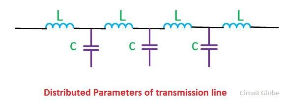
Capacitance and reactance are the main parameters of the transmission line. It is distributed uniformly along the line. These parameters are also called distributed parameters. When the voltage drops occur in transmission line due to inductance, it is compensated by the capacitance of the transmission line.

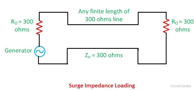
tranmssion-lineThe transmission line generates capacitive reactive volt-amperes in its shunt capacitance and absorbing reactive volt-amperes in its series inductance.The load at which the inductive and capacitive reactive volt-amperes are equal and opposite, such load is called surge impedance load.

It is also called natural load of the transmission line because power is not dissipated in transmission. In surge impedance loading, the voltage and current are in the same phase at all the point of the line. When the surge impedance of the line has terminated the power delivered by it is called surge impedance loading.

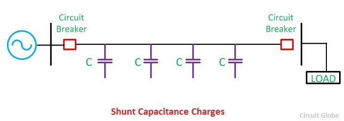
Shunt capacitance charges the transmission line when the circuit breaker at the sending end of the line is close. As shown below

Capacitance--chargingLet V = phase voltage at the receiving end
L = series inductance per phase
XL = series inductance reactance per phase
XC = shunt capacitance reactance per phase
Zo = surge impedance loading per phase

Capacitive volt-amperes (VAr) generated in the line

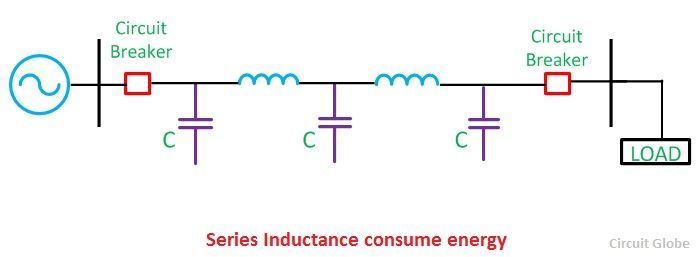
surge-1-compressorThe series inductance of the line consumes the electrical energy when the sending and receiving end terminals are closed.

series-inductance-compreInductive reactive volt-amperes (VAr) absorbed by the line

surge-equationUnder natural load, the reactive power becomes terminated, and the load becomes purely resistive.

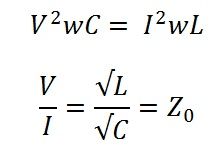
surge-impedanceAnd it is calculated by the formula given below

surge-3Surge impedance loading is also defined as the power load in which the total reactive power of the lines becomes zero. The reactive power generated by the shunt capacitance is consumed by the series inductance of the line.

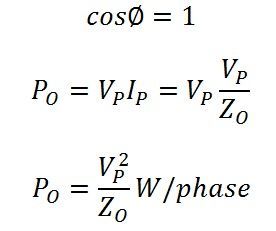
If Po is its natural load of the lines, (SIL)1∅ of the line per phase

surge-5-compressorSince the load is purely resistive,

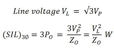
surge-impeadenceThus, per phase power transmitted under surge impedance loading is (VP2)/ZO watts, Where Vp is the phase voltage.

SURGE-55If kVL is the receiving end voltage in kV, then

SURGE-666-Surge impedance loading depends on the voltage of the transmission line. Practically surge impedance loading always less than the maximum loading capacity of the line.

If the load is less than the SIL, reactive volt-amperes are generated, and the voltage at the receiving end is greater than the sending end voltage. On the other hand, if the SIL is greater than the load, the voltage at receiving end is smaller because the line absorbs reactive power.

If the shunt conductance and resistance are neglected and SIL is equal to the load than the voltage at both the ends will be equal.

Conclusion

Surge impedance load is the ideal load because the current and voltage are uniform along the line. The wave of current and voltage is also in phase because the reactive power consumed are equal to the reactive power generated by the transmission line.

Saturday, 21 May 2022

Basic Definitions in Magnetic circuit


Magnetic Circuit

The closed path followed by magnetic lines of forces is called the magnetic circuit. In the magnetic circuit, magnetic flux or magnetic lines of force starts from a point and ends at the same point after completing its path.


Magnetic flux

The magnetic lines of force passing through a magnetic circuit is known as magnetic flux. It is denoted by a symbol ϕ and given by a formula ϕ = BA, where B is the magnetic flux density and A is the area of the cross-section in m2. The unit of magnetic flux is weber.

Magneto-motive force

Magneto-motive force or MMF is the cause for producing the magnetic flux. The MMF in a magnetic circuit depends on the number of turns(N) and the amount of current(I) flowing through it.

It is given by a formula, MMF = NI and its unit is ampere turns.

Magnetic flux density

It is the amount of magnetic flux per unit area at right angles to the flux. The unit of magnetic flux density is weber/m2 and denoted by B. The formula is given by,

  \[B=\frac{\phi}{a}\]

Magnetic field intensity

Magnetizing force or Magnetic field intensity or magnetic field strength is the MMF required to magnetize a unit length of the magnetic flux path. The unit of magnetic field intensity is AT/m and is denoted by H.

  \[H=\frac{NI}{l}\]

Reluctance

It is the opposition that the magnetic circuit offers for the flow of magnetic flux. We can also define the reluctance as the ratio of magneto-motive force to the magnetic flux. It is denoted by S and its unit is ampere-turns per weber.

  \[Reluctance(S) = \frac{MMF}{flux} \]

Permeance

Permeance is the reciprocal of reluctance. The ease with which the flux can pass through the material is known as permeance. Weber/AT is the unit of permeance.

  \[Permeance = \frac{1}{reluctance}\]

Permeability

It is the measure of the resistance of a material against the formation of a magnetic field. In simple words, the permeability of material means its conductivity for magnetic flux. The reciprocal of magnetic permeability is magnetic reluctivity. Greater permeability, greater is its conductivity.

Magnetic permeability is represented by a greek letter μ. It is given by a formula,

  \[ \mu = \frac{B}{H}\]

Relative permeability

It is the ratio of flux density of a magnetic material to the flux density produced in air by the same magnetizing force.

The formula for relative permeability is,

  \[ \mu_r = \frac{\mu}{\mu_0}\]

where μr – relative permeability of the magnetic material.

μ0 – absolute permeability of air or vacuum.

μ – absolute permeability of the magnetic material.


Analogy between Magnetic circuit and Electric Circuit

Magnetic CircuitElectric Circuit
A closed path for a magnetic flux forms a magnetic circuit.A closed path for an electric current form an electric circuit.
Magnetic flux does not flow in a magnetic circuit.Electric current always flows in an electric circuit.
MMF is the cause for producing flux.EMF is the cause for producing current.
Weber is the unit of flux.Ampere is the unit of current.

  \[Flux = \frac{mmf}{reluctance}\]

  \[Current= \frac{emf}{resistance}\]

Reluctance opposes the flow of flux.Resistance opposes the flow of current.

  \[Reluctance= \frac{l}{\mu_0 \mu_r a}\]

  \[Resistance= \frac{\rho l}{a}\]

  \[Permeance = \frac{1}{reluctance}\]

  \[Conductance= \frac{1}{resistance}\]

Flux density,

  \[B = \frac{\phi}{a}\]

Current density,

  \[J = \frac{I}{a}\]

Magnetic field intensity,

  \[H = \frac{NI}{l}\]

Electric field intensity,

  \[E = \frac{V}{d}\]

Magnetic flux lines flow from the North pole to the South pole.Electric current flows from the positive to negative terminal.

Leakage Flux And Fringing

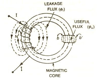
Leakage flux is defined as the magnetic flux which does not follow the particularly intended path in a magnetic circuit. 

Taking an example of solenoid you can explain the leakage flux and the fringing both.

When a current is passed through a solenoid, magnetic flux is produced by it.

Leakage flux and fringing

Most of the flux is set up in the core of the solenoid and passes through the particular path that is through the air gap and is utilised in the magnetic circuit. This flux is known as Useful flux φu.

As practically it is not possible that all the flux in the circuit follows a particularly intended path and sets up in the magnetic core and thus some of the flux also sets up around the coil or surrounds the core of the coil, and is not utilised for any work in the magnetic circuit. This type of flux which is not used for any work is called Leakage Flux and is denoted by φl.

Therefore, the total flux Φ produced by the solenoid in the magnetic circuit is the sum of the leakage flux and the useful flux and is given by the equation shown below:
leakage-flux-and-frining-eq1
Leakage coefficient

The ratio of the total flux produced to the useful flux set up in the air gap of the magnetic circuit is called a leakage coefficient or leakage factor. It is denoted by (λ).
leakage-flux-and-frining-eq2-
Fringing

The useful flux when sets up in the air gap, it tends to bulge outward at (b and b’) as shown in above figure, because of this bulging, the effective area of the air gap increases and the flux density of the air gap decreases. This effect is known as Fringing.

Fringing is directly proportional to the length of the air gap that means if the length increases the fringing effect will also be more and vice versa.


TRANSISTORS

TRANSISTORS A transistor is a semiconductor device that contains three regions separated by two distinct PN junctions. The two junctions are...

Translate