Tuesday 20 September 2016

Induction Cooktop Working


Induction cooktop, uses electromagnetism to turn cooking pans into a furnace (creating heat energy inside the pan itself, instead of shooting it out), which cooks food faster and safer with less energy.
If electricity is supplied to the inlet cooking area, then the current flows into the input coil that generates magnetic energy just above the cooking area. As a magnetic field that flexible magnet is produced as we install AC Current. a powerful electric motor but nowhere to go; we call it eddy current. As it circles inside a metal crystal structure, it exposes its energy. So a metal pan heats up and heats up any food inside it, first by moving (it transfers its heat energy directly to the food) but also by moving.
 The induction cooker looks very similar to any other ceramic cooking area, usually with separate areas where you can place pots and pans. The kitchen is usually made of solid, non-heated ceramic glass like Schott CERAN.
 Inside each cooking area, there is a metal coil with a solid wound. When you turn on the power, the switching power flows into the coil and produces an invisible, high frequency, magnetic field alternating around it. Unless there is a pan in the cooking area, no heat is generated: the cooking area remains cold. You may be wondering why we need high frequency. Although your home electricity switch is about 50Hz (50 times per second), the imported cooking area increases this by about 500–1000 times (usually up to 20–40kHz). Since that is more than the distance most of us can hear, it stops any annoying, audible buzzing. More importantly, it prevents the magnetic field from turning the pan into a cooking area.
 Place the pan in the cooking area and the magnetic field produced by the coil (shown here with blue stripes) penetrates the metal inside it.
The magnetic field pulls the electric current (eddy) into the pan, turning it into a heater (shown here in orange).
The heat from the pan flows directly into the food or water inside it (by steering).

Friday 2 September 2016

how to run fuse tube light


The tube-light is covered due to its long-term use. You may notice that the fluorescent tube-light lamp used is black on both ends. This cycle is to light up those connected tube-lights.
Have you ever considered using a reconnected tube lamp? (Usually discarded). Well here I am showing a simple cycle using a 4 diode reusable integrated light tube.
230 v AC supply
Diode -IN4007 or 159 X 4pcs

The tube-light is covered due to its long-term use. You may notice that the fluorescent tube-light lamp used is black on both ends. This cycle is to light up those connected tube-lights.
Have you ever considered using a reconnected tube lamp? (Often discarded). Well here I show a simple circuit using an integrated 4 light diode integrated light tube.

Thursday 25 August 2016

DOL Starter controling Diagram

Direct On Line Motor Starter includes tracking MCCB, Contactor and overload relay for protection. An electromagnetic contactor that can be turned on is a thermal overload relay under error conditions.The contactor controls with the start and stop buttons, and the contact assistant on the contactor is used, across the first button, as a holder for contact. i.e. the power connector is turned off while the engine is running. Usually up to 5HP induction motor we choose the first DOL method.
Direct On Line Starter (DOL) Terms of Service:
To start, the contactor is closed, using a full line voltage on the motor stator windings. The motor will pull the highest inrush current for a very short time, the magnetic field of the metal, and the current will be limited to the Locked Rotor Current of the motor. The motor will improve the Locked Rotor Torque and start accelerating towards full speed.
As the engine speeds up, the current will start to decrease, but it will not slow down until the engine is at full speed, usually 85% of the corresponding speed. The first real current curve is the car design function, as well as the terminal voltage, and is completely independent of the car load.
The load on the motor will affect the time taken for the engine to accelerate at full speed and therefore the maximum duration of the initial current, but not the maximum initial current.
As long as the torque generated by the engine exceeds the torque of the load at all speeds during the first cycle, the engine will reach full speed.
Advantages of DOL Starter: -
1. These are the simplest types to begin with.
2. The most economical and cheapest launcher.
3. Maintenance costs are very low.
Disadvantages of DOL Starter: -
1. It pulls the highest inrush current at the start which is 6-8 times the engine limit which limits its use to motors of only 7.5 KW.
2. It will apply high thermal stress to cars which will reduce the life of the vehicles.
3. The current High Starting will lead to a voltage drop.

Wednesday 10 August 2016

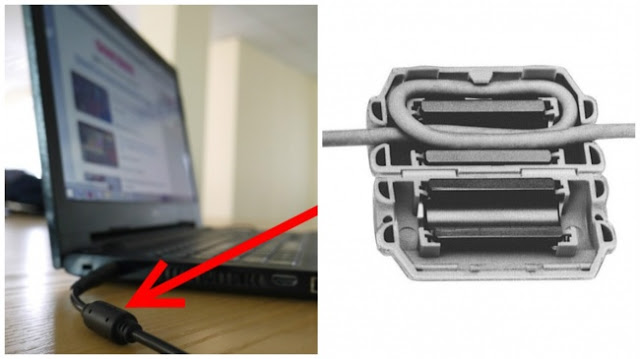
Ferrite Bead


Our laptops are our daily resource, we can use them for over 6-7 hours but have you seen the little things waiting for us at the end of it.
They always looked like useless additions that never made sense to anyone but these little cylinders called Ferrite beads. These small letters are a reason to reduce distraction.
Any device that works with power transmission also selects power from other devices. So are our laptops with power switches on the switch that enable them to transmit radio waves. This process is called EMI (electromagnetic interference). This EMI leads to unavoidable power loss with the help of this tiny cylinder. Loss of power will obviously result in less charging of your laptops to reduce that and radio frequency noise can also be reduced.

Monday 8 August 2016

Air Conditioners with Inverter technology

The latest and most effective technology available on the market today is Inverter Technology for air conditioners. Inverter technology is designed in such a way that it can save 30-50% of the electricity (units used) over normal air conditioning.
How does the air conditioner work?
The air conditioner during the cooling process, takes indoor air, cools it by passing it to the evaporator and then throws it back into our operating room with indoor air. Along with the evaporator air conditioner it also has a compressor that presses gas (refrigerator) to AC to cool itself and cool the incoming indoor air from the chamber.
In standard air conditioner:
The compressor is off or on. When turned on, it works at full capacity and consumes the full power it is designed to use. When the thermostat reaches a temperature set at AC, the compressor stops and the fan (to AC) continues to operate. When the thermostat senses that the temperature is rising, the compressor starts again.
On Air Conditioner with Inverter technology:
Inverter technology acts as an accelerator in the car. When a compressor needs more power, it gives you more power. When it needs less energy, it gives less energy. With this technology, the compressor remains open, but draws less energy or more power depending on the temperature of the incoming air and the level set by the thermostat. The speed and power of the compressor are adjusted accordingly. This technology was developed in Japan and used there successfully in air conditioners and refrigerators. This technology is currently only available on separate air conditioners.

What are the benefits of Inverter Technology?

All air conditioners are designed for high loading. So 1.5ton AC is designed for a specific room size and 1 ton for a different size. But not all rooms are the same size. A standard 1.5ton air conditioner will always operate at high power requirements when the compressor is operating. An air conditioner with inverter technology will work continuously but will only absorb most of the energy needed to maintain the desired temperature. It therefore automatically adjusts its volume according to the requirements of the cooling room. So draw very little power and use smaller power units.

Although airconditioner with Inverter Technology adjusts its volume based on the needs of the room, it is very important to install the right amount of air in the room. Please make sure you check the room and air conditioner capacity before purchase. Keep an eye out for this space as we are in the process of making a comparison of energy saving on different air conditioners.

Are Inverter technology air conditioners slow to cool?

In comparison, inverter tech AC changes the flow rate of the refrigerator based on room temperature. When the temperature is low, the flow rate is low, when the temperature is high, the flow rate is high. And it does not always turn off the compressor. It simply ensures that when the temperature setting is 25, it is maintained at that level.

So the difference is: the non-inverter AC will cool down, while the inverter AC will cool down much better. And thus one may feel that the AC inverter is neither cool nor fast.

The lesser-known benefits of Inverter Technology

Ordinary engines require 3-4 times more current (over current performance) in the beginning. Therefore the size of the inverter / generator required to use any AC or Refrigerator is greatly increased. But Inverter Technology air conditioners and refrigerators with flexible speed engines that start slowly require very little performance at first. Therefore the size of the inverter / generator needed to start is small. For example. A fixed speed of 1.5 ton AC operating at about 10 Amp current may require up to 30 Amp current when starting as well as a 5 kVA inverter / generator. But the inverter technology Air Conditioner requires about 6-7 Amp current and not too much at first and thus a 1.5 kVA or 2 kVA inverter / generator is good enough to support it.

Normal motors have a very low power factor. In commercial and industrial connectivity there is a low power factor charge and a high power factor discount. The inverter technology engine will have a power factor close to the unit (or 1) which not only results in less power consumption but also helps to get discounts on a better power factor.

If you plan to use Solar PV air conditioner, it is best to use inverter technology air conditioner or refrigerator as it not only reduces the size of the PV panel because it consumes less electricity, and reduces the size of the inverter to integrate the PV panel .

Saturday 16 July 2016

How you can use the 3 phase change over switch in home

Basically, there could be two type of phase changing device, one could be an automated one with a digital numeric relay for automatic change over and the another one is a basic manual one which have to be operated by a human. 

For typical domestic use, the device illustrated bellow have two more identical units mounted over a board with some indications regarding the number of phase available and the currently applied change over status.
The red, yellow and blue indicating lights will be in two sets in which the first set will be pointing towards the availability and healthiness of all the respective three phases at the incoming side of the device. By looking at these indication, one can determine that out three phases, which phase is available. 
Similarly the second set of indication lamp is showing the status of the three phases at the outgoing end of the device (Which will be the actual status of the three phases being fed to your home).

whenever there will be an phase outage due to faults or blown fuses at the power distribution feeder end, both sets of same coloured indication lamps will stop glowing to which phase they are assigned for (e.g. if only both sets of Yellow and Blue indication lamps are working that implicates that power supply to Red phase have been disrupted).

And now comes the part where the actual operation of the phase converter/selector will be done. There would be three similar rotary switches with three/four similar markings on it, so lets pick one switch for ease of understanding. Normally, the following would be the positions of the selector switch, for R Phase selection, the knob on switch will be indicating 1 or R. For Y-Phase, the knob will be positioned on 2 or Y and similar for the 3rd of Y phase.  

Suppose the Red indication lamps are not working, but other two are working, then the switched have to be adjusted so that only Y and B phase will be supplied further, hence the R-Phase's knob will be rotated and can be placed on either position number 2 or 3 from its earlier position of 1 so that the power line of R phase is connected to that of Y or B-Phase.

So, when the above mechanism is applied, all the 3 indication lamp on the second set will start working although the one indication lamp on the incomer side is still dark, this shows that the changeover have been completed successfully.

Things to remember !!
  • Never ever do this change-over operation with your main supply on, in order to avoid a possible flashover, always drop the main MCB of your home before operating the device.
  • Never ever use this change over device if you have a direct 3-phase device like flour-mill or water pump of high capacity as the two similar phase will damage the device.
  • Always remember to re-position the knobs to its original position once the phase have been restored if the damage caused by heavy flow of current over a single phase have to be avoided.

Thursday 14 July 2016

Working of tester

A Neon screwdriver or tester is commonly used to check the live wires. If the circuit is live, the neon bulb glows. We can also name it as voltage testing device. However the terms Phase checker, Line tester, Live checker and Positive presence checker is also used to identify the instrument. Here is the full construction with all parts indicated.

    Metal Rod:
    It is a metallic rod. The lower tip of the rod is specially chamfered to a specific screw design. This end is connected with the live wire. The upper end of this rod is completely cylindrical and it joins with the resistor.
    Resistor
    Resistor reduces the amount of current in the circuit. This current reduction provides a safe limit for the neon bulb. Next to resistor, the neon bulb is connected.
    Neon Bulb
    The neon bulb is used as the current indicator. When connected to live circuit, this neon bulb glow and we can know that circuit is live. If there is no current the bulb will not glow.
    Spring Elements
    Next to neon bulb a metallic conductive spring element is connected. It serves as a bridge or junction between the bulb and cap.
    Cap
    Next to spring a cap connects. This cap serves two purposes. Its internal sides keep all the equipment tightly pressed within the plastic assembly. Whereas its external side in pressed by the finger. (Full working explained in the working section)
    Clip
    A clip is conventionally connected with the cap.
    Plastic Assembly
    The plastic assembly surrounds the whole arrangement and its purpose is to insulate the entire design from human body so as to prevent shock and hazardous conditions.
    Working
    During working the low end of the metallic rod is connected with the live wire whereas the upper end of the cap is pressed by the human finger. The internal resistance of tester connects in series with the human body. Remember that this internal resistance is very high typically it is the order 200 k. Now the circuit completes and limited current runs through the human body. This current also flows through the neon bulb and it lights up if the circuit is live.
    There are a few precautions that should be employed while using the tester. However, two most important precautions are mentioned here:
    • The tester should only be used when you are sure that voltage is within 500 V. Also make sure that proper resistor is connected. Never connect the instrument until you are 100% sure.
    • Always use the good quality instrument, you can save a few bucks on low-quality material but it can harm your life.

    Types of source

      Ideal Voltage Source:  An ideal voltage source is capable to maintain the constant voltage across its terminals. The voltage across the vo...

    Translate