Saturday 16 April 2022

ADVANTAGES OF PER UNIT SYSTEM


PER UNIT SYSTEM

The per-unit system expressed the voltages, currents, powers, impedances, and other electrical quantities basis by the equation:

Quantity per unit (pu) = Actual value/ Base value of quantity

ADVANTAGES OF PER UNIT SYSTEM

  1. While performing calculations, referring quantities from one side of the transformer to the other side serious errors may be committed. This can be avoided by using per unit system.
  2. Per unit impedances of electrical equipment of similar type usually lie within a narrow range, when the equipment ratings are used as base values.
  3. Manufacturers usually specify the impedances of machines and transformers in per unit or percent of name plate ratings.
  4. Transformers can be replaced by their equivalent series impedances.
  5. Reduced calculations in three-phase systems.
  6. For apparatus of the same general type the p.u. and volt drops or losses are in the same order, regardless of size.

PER UNIT CONVERSION PROCEDURE OF SINGLE PHASE

  1. Pick a VA base for the entire system, Sbase
  2. Pick a voltage base for each different voltage level, Vbase.
  3. Voltage bases are related by transformer turns ratios.
  4. Voltages are line to neutral.
  5. Calculate the impedance base, Zbase = (Vbase)2/Sbase
  6. Calculate the current base, Ibase =Vbase/Zbase
  7. Convert actual values to per unit
  8. Convert to per unit (p.u.) (many problems are already in per unit)
  9. Solve
  10. Convert back to actual as necessary

Friday 8 April 2022

 FLUORESCENT LAMP (LOW-PRESSURE MERCURY VAPOR LAMP)

Fluorescent lamp is a hot cathode low-pressure mercury vapor lamp;

Construction 

It consists of a long horizontal tube, The tube contains small quantity of argon gas and certain amount of mercury, at a pressure of 2.5 mm of mercury. The construction of fluorescent lamp is shown in Fig.  Normally, low-pressure mercury vapor lamps suffer from low efficiency and they produce an objectionable colored light. Such drawback is overcome by coating the inside of the tube with fluorescent powders. They are in the form of solids, which are usually knows as phosphors.

A glow starter switch contains small quantity of argon gas, having a small cathode glow lamp with bimetallic strip is connected in series with the electrodes, which puts the electrodes directly across the supply at the time of starting. A choke is connected in series that acts as ballast when the lamp is running, and it provides a voltage impulse for starting. A capacitor of 4μF is connected across the starter 

 Working 

At the time of starting, When supply is switched on, the starter terminals are open circuited and full supply voltage appeared across these terminals, due to low resistance of electrodes and choke coil. The small quantity of argon gas gets ionized, which establishes an arc with a starting glow. This glow warms up the bimetallic strip thus glow starts gets short circuited. Hence, the two electrodes come in series and are connected across the supply voltage. Now, the two electrodes get heated and start emitting electrons due to the flow of current through them. These electrons collide with the argon atoms present in the long tube discharge that takes place through the argon gas. So, in the beginning, the lamp starts conduction with argon gas as the temperature increases, the mercury changes into vapor form and takes over the conduction of current. In the mean time, the starter potential reaches to zero and the bimetallic strip gets cooling down. As a result, the starter terminals will open. This results breaking of the series circuit. A very high voltage around 1,000 V is induced,  this induced voltage is quite sufficient to break down the long gap. Thus, more number of electrons collide with argon and mercury vapor atoms. The excited atom of mercury gives UV radiation, which fall on  fluorescent material thus emitted light.

Advantages of fluorescent lamp 
The fluorescent lamp has the following advantages:
 o High efficiency.
 o The life of the lamp is three times of the ordinary filament lamp. 
o The quality of the light obtained is much superior. 
o Less chances of glare.
 o These lamps can be mounted on low ceiling, where other light sources would be unsatisfactory. 

disadvantages: 
o The initial cost is high because of choke and starter. 
o The starting time as well as the light output of the lamp will increases because of low ambient temperature.
 o Because of the presence of choke, these lamps suffer from magnetic humming and may cause disturbance.
 o The stroboscopic effect of this lamp is objectionable.


Thursday 7 April 2022

Illumination

 Nature of light 

Light is a form of electromagnetic energy radiated from a body and human eye is capable of receiving it. Light is a prime factor in the human life as all activities of human being ultimately depend upon the light.

TERMS USED IN ILLUMINATION 

The following terms are generally used in illumination. 

Color

 The energy radiation of the heated body is monochromatic, i.e. the radiation of only one wavelength emits specific color. The wavelength of visible light lies between UNIT 1 4,000 and 7,500 Å. The color of the radiation corresponding to the wavelength is shown in Fig. 6.1. 

Light: 

It is defined as the radiant energy from a hot body that produces the visual sensation upon the human eye. It is expressed in lumen-hours and it analogous to watthours, which denoted by the symbol ‘Q’.

 Luminous flux: 

It is defined as the energy in the form of light waves radiated per second from a luminous body. It is represented by the symbol ‘φ’ and measured in lumens. 

Ex: Suppose the luminous body is an incandescent lamp. 

The total electrical power input to the lamp is not converted to luminous flux, some of the power lost through conduction, convection, and radiation, etc. Afraction of the remaining radiant flux is in the form of light waves lies in between the visual range of wavelength, i.e. between 4,000 and 7,000 Å, as shown in Fig

Solid angle 

Solid angle is the angle subtended at a point in space by an area, i.e., the angle enclosed in the volume formed by numerous lines lying on the surface and meeting at the point (Fig. 6.5). It is usually denoted by symbol ‘ω’ and is measured in steradian.


Luminous intensity

 Luminous intensity in a given direction is defined as the luminous flux emitted by the source per unit solid angle
 Luminous flux emitting from the source
It is denoted by the symbol ‘I’ and is usually measured in ‘candela’. Let ‘F’ be the luminous flux crossing a spherical segment of solid angle ‘ω’. Then luminous intensity I =d@/dt lumen/steradian or candela.

Lumen: 

It is the unit of luminous flux. It is defined as the luminous flux emitted by a source of one candle power per unit solid angle in all directions. 
Lumen = candle power of source × solid angle. Lumen = CP × ω 
Total flux emitted by a source of one candle power is 4π lumens. 

Candle power (CP) 

The CP of a source is defined as the total luminous flux lines emitted by that source in a unit solid angle.

Illumination

 Illumination is defined as the luminous flux received by the surface per unit area. It is usually denoted by the symbol ‘E’ and is measured in lux or lumen/m2 or meter candle or foot candle. 

Lux or meter candle

 It is defined as the illumination of the inside of a sphere of radius 1 m and a source of 1 CP is fitted at the center of sphere.

Brightness

 Brightness of any surface is defined as the luminous intensity pen unit surface area of the projected surface in the given direction. It is usually denoted by symbol ‘L’. If the luminous intensity of source be ‘I’ candela on an area A, then the projected area is Acos θ. 

Mean horizontal candle power (MHCP) 

        MHCP is defined as the mean of the candle power of source in all directions in horizontal plane.
 Mean spherical candle power (MSCP)

         MSCP is defined as the mean of the candle power of source in all directions in all planes. 
Mean hemispherical candle power (MHSCP) 

        MHSCP is defined as the mean of the candle power of source in all directions above or below the horizontal plane.

Reduction factor

         Reduction factor of the source of light is defined as the ratio of its mean spherical candle power to its mean horizontal candle power.

Lamp efficiency

 It is defined as the ratio of the total luminous flux emitting from the source to its electrical power input in watts. 
It is expressed in lumen/W
Specific consumption It is defined as the ratio of electric power input to its average candle power.

 Space to height ratio

 It is defined as ratio of horizontal distance between adjacent lamps to the height of their mountings.

Coefficient of utilization or utilization factor 

It is defined as the ratio of total number of lumens reaching the working plane to the total number of lumens emitting from source.

Maintenance factor 

It is defined as the ratio of illumination under normal working conditions to the illumination when everything is clean. 

Depreciation factor 

It is defined as the ratio of initial illumination to the ultimate maintained illumination on the working plane.

Waste light factor 

            When a surface is illuminated by several numbers of the sources of light, there is certain amount of wastage due to overlapping of light waves; the wastage of light is taken into account depending upon the type of area to be illuminated. Its value for rectangular area is 1.2 and for irregular area is 1.5 and objects such as statues, monuments, etc.

 Absorption factor 

Normally, when the atmosphere is full of smoke and fumes, there is a possibility of absorption of light. Hence, the total lumens available after absorption to the total lumens emitted by the lamp are known as absorption factor.

Beam factor 

        It is defined as the ratio of ‘lumens in the beam of a projector to the lumens given out by lamps’. Its value is usually varies from 0.3 to 0.6. This factor is taken into account for the absorption of light by reflector and front glass of the projector lamp. 


LAWS OF ILLUMINATION

 Mainly there are two laws of illumination. 
1. Inverse square law.
 2. Lambert's cosine law.

Inverse square law 

This law states that ‘the illumination of a surface is inversely proportional to the square of distance between the surface and a point source’.

Proof: Let, ‘S’ be a point source of luminous intensity ‘I’ candela, the luminous flux emitting from source crossing the three parallel plates having areas A1 A2, and A3 square meters, which are separated by a distances of d, 2d, and 3d from the point source respectively as shown in Fig.
Inverse square law
Luminous flux reaching the area A1 = luminous intensity × solid angle
∴ Illumination 'E1' on the surface area 'A1' is:
Similarly, illumination 'E2' on the surface area A2 is:
and illumination ‘E3’ on the surface area A3 is:


2. Lambert’s Cosine Law:

Very often the illuminated surface is not normal to the direction of light as AC in Fig. but is inclined as AB. The area over which the light is spread is then increased in the ratio-

According to this law the illumination at any point on a surface is proportional to the cosine of the angle between the normal at that point and the direction of luminous flux.


Thursday 24 March 2022

Component of an HVDC Transmission System

HVDC system has the following main components

    1. Converter Station
    2. Converter Unit
    3. Converter Transformers
    4. Filters
      1. AC filter
      2. DC filter
      3. High-frequency filter
    5. Reactive Power Source
    6. Smoothing Reactor
    7. HVDC System Pole
  • Converter Station
    The terminal substations which convert an AC to DC  are called rectifier terminal while the terminal substations which convert DC to AC are called inverter terminal. Every terminal is designed to work in both the rectifier and inverter mode. Therefore, each terminal is called converter terminal, or rectifier terminal. A two-terminal HVDC system has only two terminals and one HVDC line.

Converter Unit

The conversion from AC to DC and vice versa is done in HVDC converter stations by using three-phase bridge converters. In HVDC transmission a 12-pulse bridge converter is used. 

Converter Transformer
  • The converter transformer converts the AC networks to DC networks or vice versa. They have two sets of three phase windings. The AC side winding is connected to the AC bus bar, and the valve side winding is connected to valve bridge.These windings are connected in star for one transformer and delta to another.

    The AC side windings of the two, three phase transformer are connected in stars with their neutrals grounded. The valve side transformer winding is designed to withstand alternating voltage stress and direct voltage stress from valve bridge. There are increases in eddy current losses due to the harmonics current. The magnetisation in the core of the converter transformer is because of the following reasons.

    • The alternating voltage from AC network containing fundamentals and several harmonics.
    • The direct voltage from valve side terminal also has some harmonics.

        Filters

      The AC and DC harmonics are generated in HVDC converters. The AC harmonics are injected into the AC system, and the DC harmonics are injected into DC lines. The harmonics have the following disadvantages.

      1. It causes the interference in telephone lines.
      2. Due to the harmonics, the power losses in machines and capacitors are connected in the system.
      3. The harmonics produced resonance in an AC circuit resulting in over voltages.
      4. Instability of converter controls.

      The harmonics are minimised by using the AC, DC and high-frequency filters. The types of filter are explained below in details.

      • AC Filters – The AC filters are RLC circuit connected between phase and earth. They offered low impedances to the harmonic frequencies. Thus, the AC harmonic currents are passed to earth. Both tuned and damped filters are used. The AC harmonic filter also provided a reactive power required for satisfactory operation of converters.
      • DC Filters  – The DC filter is connected between the pole bus and neutral bus. It diverts the DC harmonics to earth and prevents them from entering DC lines. Such a filter does not require reactive power as DC line does not require DC power.
      • High-Frequency Filters – The HVDC converter may produce electrical noise in the carrier frequency band from 20 kHz to 490 kHz. They also generate radio interference noise in the megahertz range frequencies. High-frequency filters are used to minimise noise and interference with power line carrier communication. Such filters are placed between the converter transformer and the station AC bus.
      • Reactive Power Source

        Reactive power is required for the operations of the converters. The AC harmonic filters provide reactive power partly. The additional supply may also be obtained from shunt capacitors synchronous phase modifiers and static var systems. The choice depends on the speed of control desired.

        Smoothing Reactor

        Smoothing reactor is an oil filled oil cooled reactor having a large inductance. It is connected in series with the converter before the DC filter. It can be located either on the line side or on the neutral side. Smoothing reactors serve the following purposes.

        1. They smooth the ripples in the direct current.
        2. They decrease the harmonic voltage and current in the DC lines.
        3. They limit the fault current in the DC line.
        4. Consequent commutation failures in inverters are prevented by smoothing reactors by reducing the rate of rising of the DC line in the bridge when the direct voltage of another series connected voltage collapses.
        5. Smoothing reactors reduce the steepness of voltage and current surges from the DC line. Thus, the stresses on the converter valves and valve surge diverters are reduced.

        HVDC System Pole

        The HVDC system pole is the part of an HVDC system consisting of all the equipment in the HVDC substation. It also interconnects the transmission lines which during normal operating condition exhibit a common direct polarity with respect to earth. Thus the word pole refers to the path of DC which has the same polarity with respect to earth. The total pole includes substation pole and transmission line pole.

Wednesday 23 March 2022

Power Factor

 Power Factor

 AC power has three components – 

1,Real power(P) measured in watts

2.Apparent power(S) measures in volt amperes 

3.Reactive power Q measured in reactive volt 

Definition of power factor :

In electrical engineering, the power factor of an AC electrical power system is defined as the ratio of the real power absorbed by the load to the apparent power flowing in the circuit.It refers to the fraction of total power (apparent power) which is utilized to do the useful work called active power.

  • Low power factor results when KW is small in relation to KVA. 
  • The inductive loads causes large KVAR in the systems which includesTransformer , Induction motor, Induction generator (wind mill generators), High intensity discharge lightening. These inductive loads consume major portions of the power consumed in the industries. 
  • Reactive power (KVAR) required by the inductive load increases the amount of the apparent power (KVA) in the distribution system. This increase in the reactive and the apparent power results in the large angle and thus the cosine (or power factor) increase.
Advantages of improved Power Factor:

  • Real power is given by P = VIcosφ. The electrical current is inversely proportional to cosφ for transferring a given amount of power at a certain voltage. Hence higher the pf lower will be the current flowing. A small current flow requires a less cross-sectional area of conductors, and thus it saves conductors and money.
  • From the above relation, we see having a poor power factor increases the current flowing in a conductor, and thus copper loss increases. A large voltage drop occurs in the alternator, electrical transformer, and transmission, and distribution lines – which gives very poor voltage regulation.
  • The KVA rating of machines is also reduced by having a higher power factor, as per the formula:

Hence, the size and cost of the machine are also reduced.

This is why the electrical power factor should be maintained close to unity – it is significantly cheaper.

Disadvantages of low power factor

Let us consider, load as P is supplied at terminal voltage V and at power factor cosΦ by a 3-phase balanced system then load current is given by

Where P is the real power (watt) From the above expression for a given load, it is clear that if the power factor is low, the load current will be higher. The larger the load current due to low power factor results in the following effects

1) Effect on transmission lines: For the fixed active power to be transmitted over the line, the lower the power factor, the higher will be the load current to be carried by the line. Since the maximum permissible current density of the line conductor is fixed, the cross –sectional area of the conductor is to be increased in order to carry larger current. This results in an increased volume of the conductor material which in turn increases the capital cost of transmission lines. 

2) Further, Increases in the current causes increase in the line losses with a reduction in the efficiency of the line. Also the line voltage regulation is poor. 

3) Effect on transformer: A reduction in the current increase in the line losses with a reduction in the efficiency of the line.

4) Voltage regulation becomes poor at low power factor. Current at low lagging power factor causes a greater voltage drop in alternators, transformers, and transmission lines causing to have low power supply at the receiving end. To keep the receiving end voltage within permissible limits, extra equipment (i.e., voltage regulators) is required that increases the overall cost of the system.

5)Effect on switchgear and bus bar: The lower the power factor at which a given power is to be supplied, the larger is the cross –sectional area of the bus bar and the larger is the contact surface of the switchgear

6) Effect on generators: With a lower power factor, the KW capacity of agenerator is reduced. The power supplied by the exciter is increased. The generator copper losses are increased, which results in low efficiency of the generator. 

7) Effect on prime movers: When the power factor is increased, the alternator develops more reactive KVA i.e. the reactive power generated is more. This requires a certain amount of power to be supplied by the prime mover. So, a part of prime mover capacity is idle and it represents a dead investment. The efficiency of the prime mover is reduced.

 8) Effect on existing power system: For the same active power, the operation of an existing power system at a lower power factor necessitates the overloading of the equipment during full load.

Describe the range of power factor and meaning of lagging and leading power factor.

The power factor is defined as the ratio of the real power absorbed by the load to the apparent power

In case of perfectly sinusoidal waveform P,Q and S can be expressed as the vectors that form a vector triangle such that 

If is the phase angle between the current and the voltage then the power factor is equal to the cosine of the angle 

  • Since the units are consistent, the power factor is by definition a dimensionless number between -1 to 1.
  • When the power factor is 0, the energy flow is entirely reactive and the stored energy in the load returns to the source in each cycle.
  • When the power factor is 1 all the energy supplied by the source is consumed by the load.
  • power factors are usually stated as lagging or leading to show the sign of
  • Capacitive loads are leading and the inductive loads are lagging.
Avoiding of Low power factor without using Power factor improvement devices: 

1) Single phase capacitor start and capacitor run motor can be used as electric drives for better power factor

2)Three phase induction motor and transformer can be loaded to its higher load condition so that power factor at higher load is more

3) If load is shared by three phase induction motor and three phase synchronous motor then synchronous motor can be run in over excitation mode by increasing its excitation so that it runs with leading power factor and induction motor will run at lagging power factor, then overall power factor of the system improves

Q. Poor power factor reduces the handling capacity of the plant. Justify your answer

Ans:  

  • Poor power factor reduces the handling capacity of all the elements of the system 
  • For low value of power factor (lagging) increases the KVAR i.e. reactive component i.e. reactive component of the system and hence full power is not utilized and hence power handling capacity reduces. 
  • All the above drawbacks of lower power factor suggest that P.F. must be improved at least up to a value of 0.8, 0.85. 
  • For the industrial consumers, the power supplying company insist on P.F. improvement. The power tariffs are revised to impose penalties if the P.F. is poor, lesser than 0.8. 
  • They are advised to install Power factor improvement devices. 


Wednesday 16 March 2022

EHVAC Vs HVDC TRANSMISSION


EHVAC Vs HVDC TRANSMISSION

HVDC vs HVAC Transmission Systems

HVDC stands for High Voltage Direct Current while HVAC stands for High Voltage Alternating Current. These are typically the rate of voltage, either DC (HVDC) or AC (HVAC) that are employed for energy transmission over long distances. HVDC is preferred to be utilized for transmitting energy over long distances, commonly more than 375 miles.

HVDC vs HVAC Transmission Systems (Reference: tdworld.com)

Nowadays, both formats of power transmission are employed all over the world. While these both have some advantages and disadvantages, we will explain each of them briefly in this post below based on different characteristics to discuss the HVDC vs HVAC transmission systems fundamentally.

Cost of Transmission

We understand that energy transmission over long-distance application needs high voltages. The power is used in terminal stations that modify the voltage rates. So, the total price of transmission is based on the cost of the transmission line and the terminal source’s situation.

Terminal Station

The great number of voltages transmitted within electrical terminal sources and their operation are introduced as the voltage conversion. The system employed for voltage conversion at these sources is mainly transformers in the case of AC types that is converted between low and high Voltages. Whereas in the case of DC type, the terminal sources utilize IGBTs or thyristor-based converters for modification between low and high DC voltage.

Since the transformers are less expensive and more reliable than these solid-state converters, the AC terminal sources are cheaper than DC types. Thus, the voltage modification in AC is less costly than DC forms.

Transmission Line

The transmission line price is based on the number of conductors being employed and the price of the transmission tower.

In the aspect of conductors being employed for transmission systems, the HVDC transmission type needs just two conductors, while the HVAC transmission form needs 3 or more than 3 instruments (including the covered conductor according to the harmful effects).

Because of the massive mechanical load on AC tower systems, their operation requires to be stronger and it should be taller and wider than HVDC transmission systems. The transmission line price rises with the distance and it is far higher than the HVDC line per 60 miles of a transmission path.


Overall Cost of Transmission

The overall cost of transmission is based on the terminal price (remains fixed) and the line price (rises with distance). As a result, the overall cost of the transmission system increases with distance.

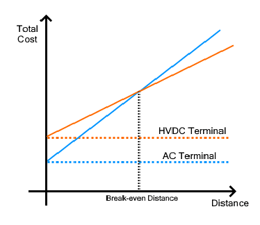
HVDC vs HVAC Transmission Systems Cost (Reference: electricaltechnology.org)

The transmission path at which the total investment cost for HVAC begins to increase is introduced as Break-even Distance. This value is evaluated around 400 – 500 miles. HVDC is a more suitable option for energy transmission in the break-even distance. Although, below this distance, HVAC is more effective than HVDC. This data can be simply understood by the previous diagram.

Flexibility

Because the HVDC transmission is employed for transmission over long-distance applications between two areas, we cannot extract power at any section in-between since it would require an expensive converter to reduce such high DC voltages. In contrast, the HVAC transmission provides flexibility using a simple and cheap device like transformers at several terminal stations to control these high voltages.

Power Losses

The HVAC power transmission format has more power wastes such as Radiation losses, Induction losses, Skin effect, Corona losses, etc.

The radiation & induction losses depend on the magnetic field variation near the HVAC conductor. A massive conductor starts operating as an antenna and radiates some power that cannot recover, while the induction wastes are the energy loss when the current is produced in close conductors based on the continuously magnetic field variation. Since DC has an identical magnetic field, the HVDC type is free from these losses.

The alternating current produced in a conductor is separated in such a method that the current density wants to compose largest at the top of the conductor and minimum at the middle; this is known as the skin effect. Because much of the cross-sectional surface is ineffective and we understand that the resistance is straightly related to the cross-sectional surface, the resistance value of the conductor rises. The DC in the system is uniformly spread because the skin effect is just based on the frequency. So, only HVAC type experience power waste according to the skin effect in this aspect of HVDC vs HVAC transmission systems.

When the voltage rises more than a specific limit, the air close to the conductor begins the ionizing process and produces sparks that lose some power; this is introduced as corona discharge. The losses of corona discharge are also based on the frequency and because DC systems have zero frequency, the corona waste in HVAC is almost 3 times higher than that in HVDC.

The Skin Effect in Detail

The skin effect forces the conductor to keep most of the current at its top and less current at the center. It is based on the frequency and directly proportional to it. It reduces the efficiency of the conductors being employed. Thus, in order to provide a larger current, the cross-sectional section of the conductor requires to be increased.

Skin Effect in HVDC vs HVAC Transmission Systems (Reference: electricaleasy.com)

So, the HVAC requires a larger diameter device to carry the equal value of current as compared to the HVDC type employing a shorter diameter conductor.

Current & Voltage Ratings of Cable

As we discussed before, the current and voltage ratings of a cable are the optimum allowable range that it can be passed. The AC systems have a peak current and voltage that is practically 1.4 times greater than its average (the average practical energy delivered) or its DC norm. But in DC type, the average and peak values are equal.


Peak and Average Values for Transmission Systems (Reference: electrical4u.com)

The conductor should be evaluated for the peak voltage and current for the HVAC type which loses almost 30% of its ideal capacity in comparison with HVDC form, which uses the complete capacity of the conductor. So, a conductor with an identical size can be more preferred in HVDC vs HVAC transmission systems.

Right-of-Way

The right of way is the right method to use the land to and from another section of land. In the exploration of HVDC type, it includes a narrower right-of-way since it can employ smaller kinds of towers with fewer conductors being applied, i.e., two in DC types and 3 in 3-phase AC systems. Also, the insulators used in the main towers should be rated for peak voltages in AC systems.

The right-of-way influences the prices of substances used and fabrication requirements for the different transmission systems. We can conclude that HVDC types have a narrower right-of-way than HVAC transmission systems.

Submarine Power Transmission

We use cables in order to move power offshores employing submarine power transmission. At the same time, the cables provide certain capacitance generated between two conductors that operate in parallel arrangement to transmit power over long-distance applications.

The capacitance value is just based on the variation in voltage which is continuously happening in AC types, and only during switching mode in DC systems. The cable does not provide energy due to such capacitance (at the receiving section) before being completely charged. The cable is discharged and charged continuously in alternating current (50 or 60 times per second) which forces the system to lose a huge power. In contrast, the cable is charged only once in DC type. As a result, the submarine power system employed HVDC for energy transmission.

Controllability of Power Flow

When we discuss the HVDC vs HVAC transmission systems in the case of controllability, HVDC form uses particular converters of IGBT semiconductors which can be switched off and on several times in a period and control the total system, while HVAC has not a controllable part for Power flow. While the converters used in HVDC are complex, they help in controlling the distribution of energy to the entire setup and also increase the harmonic performance. These developed electronic converters provide fast protection against line errors and fault clearance contrary to the HVAC types.

Circuit Breaker

The Circuit breaker is a highly important section of power transmission systems. It can cease the whole circuit operation for reaction to any fault or maintenance. The circuit breaker requires arc-extinguish abilities in the current to stop the power supply.

The direction and value of the current modify continuously in HVAC systems and the arc is typically extinguished based on the presence of several zero currents in a second that present various chances to stop the arc. Whereas in DC form, the current is fixed and there are no zero currents, so artificial zero currents should be produced employing particular circuitry to stop the arc.

As a result, in the comparison of HVDC vs HVAC transmission systems, the circuit breakers for HVAC are easy to modeling according to the “self-arc-extinguish” feature. This is while for HVDC, the circuit-breaker modeling is relatively complex and they are more costly than HVAC types.

Generating Interference

The AC systems produce a magnetic field with continuously variable values that can cause interference with the conductors in the nearby communication. Because DC types have a constant magnetic field, they do not cause such problems.

Key Differences to Contrast Hvdc vs Hvac Transmission Systems

At what follows, key differences between HVDC vs HVAC transmission systems are summarized:

  • Skin effect is zero in DC systems. Also, corona wastes are especially lower in DC type. An HVDC path has noticeably lower wastes in comparison with HVAC over long-distance applications.
  • HVDC transmission path would cost lower than an HVAC type.
  • Based on the absence of inductance value in DC type, an HVDC path provides better voltage monitoring. Also, HVDC supplies greater controllability in comparison with HVAC.
  • AC power grids are normalized for 60 Hz in some regions and 50 Hz in others. It is impractical to combine two power grids operating at different frequencies using an AC junction. An HVDC port makes this possible for power grids.
  • Interference with close relative lines is lower in HVDC types than an HVAC overhead line.
  • The short circuit current rate in the receiving setup is great in longer distance HVAC transmission system. An HVDC type does not chip in such circuit current of the AC form.


Conclusion

In a general comparison for HVDC vs HVAC transmission systems, HVDC transmission types have many more benefits over HVAC types, including controllability, stability, etc. HVDC systems are more cost-effective for distances greater than the break-even point. Submarine HVDC instruments can be more reliable for use in offshore wind farms as they are less expensive than undersea HVAC wires. As a result, there is an increasing tendency to choose the HVDC transmission type. However, HVAC systems are also employed because they have their particular advantages in distribution and transmission, such as they can be simply stepped down and stepped up which is an important matter in certain applications. HVDC is practically a supplement for AC forms rather than an opponent.


Proximity effect

 Definition: When the conductors carry the high alternating voltage then the currents are non-uniformly distributed on the cross-section area of the conductor. This effect is called proximity effect. The proximity effect results in the increment of the apparent resistance of the conductor due to the presence of the other conductors carrying current in its vicinity.

When two or more conductors are placed near to each other, then their electromagnetic fields interact with each other. Due to this interaction, the current in each of them is redistributed such that the greater current density is concentrated in that part of the strand most remote from the interfering conductor.

If the conductors carry the current in the same direction, then the magnetic field of the halves of the conductors which are close to each other is cancelling each other and hence no current flow through that halves portion of the conductor. The current is crowded in the remote half portion of the conductor.

When the conductors carry the current in the opposite direction, then the close part of the conductor carries, the more current and the magnetic field of the far off half of the conductor cancel each other. Thus, the current is zero in the remote half of the conductor and crowded at the nearer part of the conductor.

If DC flows on the surface of the conductor, then the current are uniformly distributed around the cross section area of the conductor. Hence, no proximity effect occurs on the surface of the conductor.

The proximity effect is important only for conductor sizes greater than 125 mm2.Correction factors are to be applied to take this fact into account.

If Rdc – uncorrected DC level of the core
Ys – skin effect factor, i.e., the fractional increment in resistance to allowing for skin effect.
yp – proximity effect factor, i.e., the fractional increment in resistance to allowing for skin effect.
Re –  effective or corrected ohmic resistance of the core.
The allowance for proximity effect is made, the AC resistance of the conductor becomes
proximity-effect-equation-1The resistance Rdc is known from stranded tables.

Factors Affecting the Proximity Effect

The proximity effect mainly depends on the factors like conductors material, conductor diameter, frequency and conductor structure. The factors are explained below in details

  1. Frequency – The proximity increases with the increases in the frequency.
  2. Diameter – The proximity effect increases with the increase in the conductor.
  3. Structure – This effect is more on the solid conductor as compared to the stranded conductor  (i.e., ASCR) because the surface area of the stranded conductor is smaller than the solid conductor.
  4. Material – If the material is made up of high ferromagnetic material then the proximity effect is more on their surface.

How to reduce Proximity Effect?

The proximity effect can be reduced by using the ACSR (Aluminum Core Steel Reinforced) conductor. In ACSR conductor the steel is placed at the centre of the conductor and the aluminium conductor is positioned around steel wire.

The steel increased the strength of the conductor but reduced the surface area of the conductor. Thus, the current flow mostly in the outer layer of the conductor and no current is carried in the centre of the conductor. Thus, reduced the proximity effect on the conductor.

Types of source

  Ideal Voltage Source:  An ideal voltage source is capable to maintain the constant voltage across its terminals. The voltage across the vo...

Translate