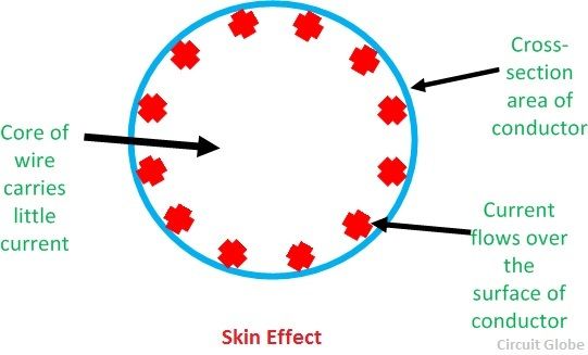
Friday 6 May 2022

Skin Effect

 Skin Effect

The non-uniform distribution of electric current over the surface or skin of the conductor carrying a.c is called the skin effect. In other words, the concentration of charge is more near the surface as compared to the core of the conductor. The ohmic resistance of the conductor is increased due to the concentration of current on the surface of the conductor.

Skin effect increases with the increase in frequency. At low frequency, such as 50Hz, there is a small increase in the current density near the surface of the conductor; but, at high frequencies, such as radio frequency, practically the whole of the currents flows on the surface of the conductor. If d.c current (frequency=0) is passed in a conductor, the current is uniformly distributed over the cross-section of the conductors.

skin-effect

Why skin effect occurs?

Let us consider the conductor is made up of a number of concentric cylinders. When a.c is passed in a conductor, the magnetic flux induces in it. The magnetic flux linking a cylindrical element near the center is greater than that linking another cylindrical element near the surface of the conductor. This is due to the fact that the center cylindrical element is surrounded by both the internal as well as the external flux, while the external cylindrical element is surrounded by the external flux only.

The self-inductance in the inner cylindrical element is more and, therefore, will offer a greater inductive reactance than the outer cylindrical element. This difference in the inductive reactance gives a tendency to the current to concentrate towards the surface or skin of the conductor.

The current density is maximum at the surface of the conductor and minimum at the center of the conductor. The effect is equivalent to a reduction of the cross-section area of the conductor and, therefore the effective resistance of the conductor is increased.

Factors affecting skin effect

  1. Frequency – Skin effect increases with the increase in frequency.
  2. Diameter – It increases with the increase in diameter of the conductor.
  3. The shape of the conductor – Skin effect is more in the solid conductor and less in the stranded conductor because the surface area of the solid conductor is more.
  4. Type of material – Skin effect increase with the increase in the permeability of the material (Permeability is the ability of material to support the formation of the magnetic field).

Points-to-remember

  1. The Skin effect is negligible if the frequency is less than the 50Hz and the diameter of the conductor is less than the 1cm.
  2. In the stranded conductors like ACSR (Aluminium Conductor Steel Reinforced) the current flows mostly in the outer layer made of aluminum, while the steel near the center carries no current and gives high tensile strength to the conductor. The concentration of current near the surface enabled the use of ACSR conductor.

Main Components of Overhead Lines and choice of conductors

 Main Components 
& Conductor Materials Used in Overhead Lines

Main Components of Overhead Lines

An overhead line may be used to transmit or distribute electric power. The successful operation of an overhead line main Components of Overhead Lines depends to a great extent upon the mechanical design of the line. While constructing an overhead line, it should be ensured that the mechanical strength of the line is such so as to provide against the most probable weather conditions.

Conductors :

The lines used for the transmission and distribution of electricity are called conductors. The conductor is mainly used to carry the electrical energy from the generating station to the distribution substation and from the distribution centre to the consumer load centres. Conductors are the most expensive component in the overhead line transmission as the different parameters are taken into consideration for the material selection of the conductor. The size, shape and type of material used are the main factors in selecting conductors.

During the material selection, the current rating and the span of current-carrying factors will play a key role such as they will decide the type of composition that should be used for the conductors. The type of materials used for the conductors are:

a. Copper: The main factor of using copper is that it holds the highest conductivity factor. The most commonly used material for the conductors is copper. There are mainly three kinds of copper such as soft-drawn, medium-drawn and Hard-drawn. The hard drawn copper is used for the construction of the conductors. The main factors for selecting hard drawn copper as it has less elastic factor and more mechanical strength which will make the conductor withstand high current. Due to expensive factors, copper is not directly used for overhead transmission.

b. Aluminium: the most commonly used conductors are made up of aluminium as it is less costly. The weight is also lighter compared to the copper, this advantage makes the pole strength factor decreases. ACSR and AAAC conductors are mainly used for the transmission lines. ACSR is made up of small strands of aluminium twisted together used for the conductors. The twisting of the aluminium strands will give more tensile strength which is used to withstand heavy currents. The main disadvantage of aluminium is it has less conductivity compared to copper and less tensile strength.

c. Galvanized Steel: the major advantage of Galvanized steel is it is cost-effective. It is used for short-distance power transmissions as it consists of some drawbacks such as low conductivity, high resistance and less tensile strength.

d. Cadmium Copper and Copper weld steel are rarely used because of their most expensive factor.

Insulators :

Insulators are provided on the supports (poles or towers) to support conductors such that necessary insulation is provided to supports from conductors. This further prevents leakage currents from conductor to earth through supports. Insulators also prevent short-circuiting between conductors and metalwork. The most commonly used insulating materials are porcelain, glass, and Stealite. The various types of insulators are,

Pin-type insulators
Suspension type insulators
Strain insulators
Shackle insulators and
Stay insulators.

Supports :

The function of line supports is to support the conductors and to keep the conductors at a suitable level above the ground. Generally, poles or towers are chosen as supports. These are employed depending upon the working voltage and the regions where they are used. Poles or towers are of various types like,

Wooden poles
Steel poles
RCC poles and
Lattice steel towers.

Cross-arms and Clamps :

These are provided on pole structures to support the insulators and conductors. These are made up of either wood or steel angle sections.


Guys and Stays :

These are employed to resists the lateral forces at the termination or angle poles by fastening the braces or cables to the poles.


Lightning Arrestors :

It is a device used to provide protection against traveling waves or high voltage produce due to lightning by discharging the excessive-high voltage of the line to the ground.

Fuses and Isolating Switches :

These are used to isolate different parts of the transmission system.

Earth Wire :

Earth wire is made run on the top of the towers in order to protect the line against lightning.

Vee-Guards :

To ensure public safety, these are provided below the base overhead line along the street.

Guard Wires :

The guard wires are provided above or below transmission lines while crossing the communication lines and are solidly connected to the earth.

Miscellaneous Components :

Phase plates, bird guards, danger plates, barbed wires, vibration-dampers, top hampers, beads for jumpers, etc. The phase plates give information about various phases used, the barbed wire, and are wounded to poles at a height of 2.5 meters in order to prevent the climbing of unauthorized persons. However, danger plates are also provided at a height of 2.5 meters from the ground level.


Voltage Source and Current Source – Ideal vs. Practical


Voltage Source and Current Source – Ideal vs. Practical

Voltage source:

Ideal Voltage Source: 

A voltage source is a device which provides a constant voltage to load at any instance of time and is independent of the current drawn from it. This type of source is known as an ideal voltage source. It has zero internal resistance.

            The graph represents the change in voltage of the voltage source with respect to time. It is                 constant at any instance of time.

Practical Voltage Source:

Voltage sources that have some amount of internal resistance are known as a practical voltage source. Due to this internal resistance, voltage drop takes place. If the internal resistance is high, less voltage will be provided to load and if the internal resistance is less, the voltage source will be closer to an ideal voltage source.A practical voltage source is thus denoted by a resistance in series which represents the internal resistance of source.
 

Current source:

 Ideal Current Source:
A current source is a device which provides the constant current to load at any time and is independent of the voltage supplied to the circuit. This type of current is known as an ideal current source; practically ideal current source is also not available. It has infinite resistance. 

The graph represents the change in current of the current source with respect to time. It is constant at any instance of time.

Practical Current source

Practically current sources do not have infinite resistance across there but they have a finite internal resistance. So the current delivered by the practical current source is not constant and it is also dependent somewhat on the voltage across it.

A practical current source is represented as an ideal current source connected with resistance in parallel.

The graph represents the current of the current source with respect to time. It is not constant but it also keeps on decreasing as the time passes.


Monday 18 April 2022

Design of Lighting Schemes

 i. Illumination Level:

This is the most vital factor because a sufficient illumination is the basic means whereby we are able to see our surroundings.

For each type of work there is a range of brightness most favourable to output i.e. which causes minimum fatigue and gives maximum output in terms of quality depends upon:

(i) The size of the objects to be seen and its distance from the observer. Greater the distance of the object from observer and smaller the size of the object, greater will be the illumination required for its proper perception and

(ii) Contrast between the object and back-ground-greater the contrast between the colour of the object and its background, greater will be the illumination required to distinguish the object properly. Objects which are seen for longer duration of time required more illumination than those for casual work. Similarly moving objects required more illumination than those for stationary objects.

ii. Uniformity of Illumination:

The human eye adjusts itself automatically to the brightness within the field of vision. If there is a lack of uniformity, pupil or iris of the eye has to adjust more frequently and thus fatigue is caused to the eye and productivity is reduced. It has been found that visual performance is best if the range of brightness within the field of vision is not greater than 3:1, which can be achieved by employing general lighting.

iii. Shadows:

In lighting installations, formation of long and hard shadows causes fatigue of eyes and therefore is considered to be a shortcoming. Complete absence of shadows altogether again does not necessarily mean an ideal condition of lighting instillations. Contrary, perhaps to popular opinion, a certain amount of shadow is desirable in artificial lighting as it helps to give shape to the solid objects and makes them easily recognised.

iv. Glare:

It may be direct or reflected i.e. it may come direct from the light source or it may be reflected brightness such as from a desk top, nickeled machine parts, or calendared paper.

Direct glare from a source of light is more common, and is more often a hindrance to vision. A glance at the sun proves that an extremely bright light source causes acute eye discomfort. Reflected glare is glare which comes to the eyes as glint or reflection of the light source in some polished surface.

v. Mounting Height:

In case of direct lighting it depends upon the type of building and type of lighting scheme employed. For rooms of large floor area, the luminaries should be mounted close to ceiling as possible. In case of indirect and semi-indirect lighting, it would be desirable to suspend luminaries enough down from ceiling to give uniform illumination.

vi. Spacing of Luminaries:

The distance of light source from the wall should be equal to one half the distances between two adjacent light sources. The distance between light fittings should not exceed 1.5 times the mounting height.

Different lighting schemes

 Different lighting schemes may be classfied as:

(i) direct lighting, (ii) indirect lighting, (iii) semi-direct lighting, (iv) semi-indirect lighting, and (v) general diffusing systems.
Lighting


(i) Direct Lighting
As the name indicates, in the form of lighting, the light from the source falls directly on the object or the surface to be illuminated. It is most commonly used type of lighting scheme. In this lighting scheme more than 90 percent of total light flux is made to fall directly on the working plane with the help of deep reflectors. Though it is most efficient but causes hard shadows and glare. It is mainly used for industrial and general out-door lighting.

direct lighting

(ii) Indirect Lighting

In this light scheme more than 90 percent of total light flux is thrown upwards to the ceiling for diffuse re­flection by using inverted or bowl reflectors. In such a system the ceiling acts as the light source, and the glare is reduced to mini­mum. The resulting illumination is softer and more diffused, the shadows are less prominent and the appearance of the room is much improved over that which results from direct lighting. It is used for decoration purposes in cinemas theatres and hotels etc. and in workshops where large machines and other obstructions would cause trouble some shadows of direct lighting is employed.


Indirect Lighting

(iii) Semi-direct System

In this lighting scheme 60 to 90 percent of the total light flux is made to fall downwards directly with the help of semi-direct reflectors, remaining light is used to illuminate the ceiling and walls. Such a lighting system is best suited to rooms with high ceilings where a high level of uniformally distributed illumination is desirable. Glare in such units is avoided by employing diffusing globed which not only improve the brightness towards the eye but improve the efficiency of the systems with reference to working place.


Semi-Direct Lighting

(iv) Semi-indirect Lighting

In this lighting scheme 60 to 90 percent of total light flux is thrown upwards to the ceiling for diffuse reflection and the rest reaches the working plane directly except for some absorption by the bowl. This lighting scheme is with soft shadows and glare free. It is mainly used for indoor light decoration purposes.


Semi-Indirect Lighting

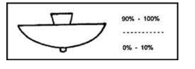
(v) General Diffusing System
In this system, luminaries are employed which have almost equal light distribution downwards and upwards.


Saturday 16 April 2022

ADVANTAGES OF PER UNIT SYSTEM


PER UNIT SYSTEM

The per-unit system expressed the voltages, currents, powers, impedances, and other electrical quantities basis by the equation:

Quantity per unit (pu) = Actual value/ Base value of quantity

ADVANTAGES OF PER UNIT SYSTEM

  1. While performing calculations, referring quantities from one side of the transformer to the other side serious errors may be committed. This can be avoided by using per unit system.
  2. Per unit impedances of electrical equipment of similar type usually lie within a narrow range, when the equipment ratings are used as base values.
  3. Manufacturers usually specify the impedances of machines and transformers in per unit or percent of name plate ratings.
  4. Transformers can be replaced by their equivalent series impedances.
  5. Reduced calculations in three-phase systems.
  6. For apparatus of the same general type the p.u. and volt drops or losses are in the same order, regardless of size.

PER UNIT CONVERSION PROCEDURE OF SINGLE PHASE

  1. Pick a VA base for the entire system, Sbase
  2. Pick a voltage base for each different voltage level, Vbase.
  3. Voltage bases are related by transformer turns ratios.
  4. Voltages are line to neutral.
  5. Calculate the impedance base, Zbase = (Vbase)2/Sbase
  6. Calculate the current base, Ibase =Vbase/Zbase
  7. Convert actual values to per unit
  8. Convert to per unit (p.u.) (many problems are already in per unit)
  9. Solve
  10. Convert back to actual as necessary

Friday 8 April 2022

 FLUORESCENT LAMP (LOW-PRESSURE MERCURY VAPOR LAMP)

Fluorescent lamp is a hot cathode low-pressure mercury vapor lamp;

Construction 

It consists of a long horizontal tube, The tube contains small quantity of argon gas and certain amount of mercury, at a pressure of 2.5 mm of mercury. The construction of fluorescent lamp is shown in Fig.  Normally, low-pressure mercury vapor lamps suffer from low efficiency and they produce an objectionable colored light. Such drawback is overcome by coating the inside of the tube with fluorescent powders. They are in the form of solids, which are usually knows as phosphors.

A glow starter switch contains small quantity of argon gas, having a small cathode glow lamp with bimetallic strip is connected in series with the electrodes, which puts the electrodes directly across the supply at the time of starting. A choke is connected in series that acts as ballast when the lamp is running, and it provides a voltage impulse for starting. A capacitor of 4μF is connected across the starter 

 Working 

At the time of starting, When supply is switched on, the starter terminals are open circuited and full supply voltage appeared across these terminals, due to low resistance of electrodes and choke coil. The small quantity of argon gas gets ionized, which establishes an arc with a starting glow. This glow warms up the bimetallic strip thus glow starts gets short circuited. Hence, the two electrodes come in series and are connected across the supply voltage. Now, the two electrodes get heated and start emitting electrons due to the flow of current through them. These electrons collide with the argon atoms present in the long tube discharge that takes place through the argon gas. So, in the beginning, the lamp starts conduction with argon gas as the temperature increases, the mercury changes into vapor form and takes over the conduction of current. In the mean time, the starter potential reaches to zero and the bimetallic strip gets cooling down. As a result, the starter terminals will open. This results breaking of the series circuit. A very high voltage around 1,000 V is induced,  this induced voltage is quite sufficient to break down the long gap. Thus, more number of electrons collide with argon and mercury vapor atoms. The excited atom of mercury gives UV radiation, which fall on  fluorescent material thus emitted light.

Advantages of fluorescent lamp 
The fluorescent lamp has the following advantages:
 o High efficiency.
 o The life of the lamp is three times of the ordinary filament lamp. 
o The quality of the light obtained is much superior. 
o Less chances of glare.
 o These lamps can be mounted on low ceiling, where other light sources would be unsatisfactory. 

disadvantages: 
o The initial cost is high because of choke and starter. 
o The starting time as well as the light output of the lamp will increases because of low ambient temperature.
 o Because of the presence of choke, these lamps suffer from magnetic humming and may cause disturbance.
 o The stroboscopic effect of this lamp is objectionable.


Types of source

  Ideal Voltage Source:  An ideal voltage source is capable to maintain the constant voltage across its terminals. The voltage across the vo...

Translate