Saturday 26 November 2022

Different Parts of transformer and their functions


transformer is the most important electrical machine used to transfer electrical energy from one circuit to another without changing its frequency. It is used either to step up or step down the voltage to minimize transmission losses in the electrical circuits. It works on the principle of electromagnetic induction.Since it is a static eectrical device so due to the absence of rotating parts, it has very high efficiency (The basic parts of transformer are its core, primary and secondary windings. Apart from these, there are many different types of equipment installed in transformers that are also considered as parts of transformer, such as its cooling arrangements, protection relay ( Buchholz relay ), HT and LT terminals and bushings, breather, conservator, oil tank, explosion vent, tap changer, etc. So let’s discuss all these different parts of transformer and their functions in detail.

Parts of transformer and their functions

Following are the various parts of transformer:

  1.  Laminated core
  2. Windings
  3. Insulating material
  4. Tank
  5. Terminals and bushings
  6. Transformer oil
  7. Tap changer
  8. Buchholz relay
  9. Oil conservator
  10. Breather
  11. Radiator and fan

From all the above listed parts of transformer, laminated soft iron core, windings, and insulating material are the basic parts of transformer. These three are available in all types of transformers. Whereas rest of all these parts of transformer can be seen generally in power transformer of rating more than 100 kVA. So let's discuss each part of transformer one by one in detail and their functions.

Laminated core

Laminated core is the most important parts of transformer, used to support the windings of transformer. It is made up of laminated soft iron material to reduce eddy current loss and hysteresis loss. Nowadays in the core of transformer laminated sheets are used to minimize eddy current losses and CRGO steel material is used to minimize hysteresis losses. The composition of core material depends on the voltage, current, and frequency of supply to the transformer.

The diameter of transformer core becomes directly proportional to copper losses and inversely proportional to iron losses or core losses.

Laminated core also provides a low reluctance path for the magnetic flux that minimize leakage flux and maximize the strength of main working flux for transformer.

Windings

In a transformer always two sets of windings are placed on laminated core and these are insulated from each other. Winding consists of several no of turns of copper conductors that is bundled together and connected in series.
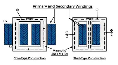
windings of transformer

The main function of windings is to carry current and produce working magnetic flux and induce mutual EMF for transformer action.

Windings are classified in two ways:

  • Based on the input and output of supply
  • Based on the voltage level of supply


Based on the input and output of the supply, windings are further classified as:

1. Primary winding:- the winding at which the input supply is connected is known as the primary winding.

2.  Secondary winding:- the winding from which output is taken to the load is known as the secondary winding.

Whereas based on the voltage level of supply, windings are further classified as:

1. High voltage (HV) winding:- the winding that is connected with higher voltage is known as high voltage winding. It is made up of a thin copper conductor with a large no of turns. It can be either  primary or secondary winding of the transformer.

2. Low voltage (HV) winding:-  the winding that is connected with lower voltage is known as low voltage winding. It is made up of a thick copper conductor with few no. of turns. It can also be either primary or secondary winding of the transformer.

Hence input and output to the transformer can be connected either on LV-winding or HV-winding as per requirement.

Why transformer windings are made up of copper?

Transformer and all other electrical machines windings are made by good quality copper material due to these properties of copper.

1. Copper is a good conductor of electricity due to its higher conductivity as compared to other materials. So this minimises the power losses in the windings.

2. Other interesting property of copper is it has higher ductility. This means it is very easy to bend conductor into tight winding around the transformer core, that helps in minimizing the amount of copper needed as well as volume and weight of copper.

Insulating material

Since insulation failure can cause the most severe damages to the transformer. So insulation and insulating material should be high grade and it is the most important part of transformer. Insulation is required between each turn of windings, between windings, winding and core, and all current-carrying parts and tank of transformer. 

The main function of insulating material is to protect transformer against short circuits by providing insulation to windings so that it does not come in contact with the core and any other conducting material.

Insulating material of transformer should have high dielectric Properties and also good mechanical strength and temperature withstand capability.

Synthetic material, papers, and cotton cloth, etc are used as insulating material in transformer.

Main Tank

Main tank is the robust part of transformer that serves mainly two purposes:

1. It protects core and windings from the external environment and provide housing for them.

2. It is used as a container for transformer oil and provides support for all other external accessories of the transformer.
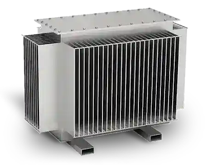
Main tank of transformer
The main tank of the transformer

Tanks are made up of fabricated rolled steel plates. They are provided with lifting hooks and inbuilt cooling tubes. In order to minimize the weight and stray losses, aluminum sheets are also being used instead of Steel plates. However, due to its light weight property, now-a-days aluminum tank is more familiar and costly than a steel tank.

Terminals and bushings

Terminals and bushings are also important parts of the transformer that are used to connecting incoming and outgoing cables of supply and load. These are connected with the ends of the windings conductor.
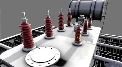
bushings of transformer

Bushings are mainly an insulators made up of porcelain or epoxy resins. They are mounted over the tank and forms a barrier between terminals and tank. They provide safe passage for the conductor connecting terminals to the windings.

As windings are of two types and so bushings are also of two types as named below:

1.     High-voltage bushing

2.     Low-voltage bushing

Transformer oil

The function of transformer oil is to provide insulation between windings as well as cooling due to its chemical properties and very good dielectric strength.


It dissipates the heat generated by the core and windings of a transformer to the external environment. When the windings of transformer gets heated due to flow of current and losses, the oil cools down the windings by circulating inside the transformer and transfer heat to the external environment through its cooling tubes.

Hydro-carbon mineral oil is used as transformer oil and acts as coolant. It is composed of aromatics, paraffin, naphthenes, and olefins.

Tap changer

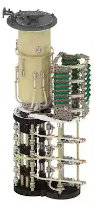
on-load tap changer


The main function of the tap changer is to regulate the output voltage of transformer by changing its turns ratio. There are two types of tap changers.

1. On-load tap changer:- in an on-load tap changer, tapping can be changed without isolating the transformer from the supply. Hence it is capable to operate without interrupting the power supply.

2. Off-load tap changer:- in off-load tap changer, the transformer needs to isolate from supply to change its tapping (turns ratio).

An automatic tap changer is also available.

Buchholz relay

Buchholz relay is the most important part of a power transformer rated more than 500kVA. It is a gas-actuated relay mounted on the pipe connecting the main tank and conservator tank.

Buchholz relay

The function of the Buchholz relay is to protect the transformer from all internal faults such as short circuit fault, inter-turn fault, etc.

When short circuit occurred in winding then it generates enough heat to decompose transformer oil into gases ( hydrogen, carbon monoxide, methane, etc). These gases move towards the conservator tank through a connecting pipe, then due to these gases, Buchholz relay gets activated. It sends signal to trip and alarm circuits and activate it. Then circuit breaker disconnects the transformer from the supply.

Oil conservator

The function of the oil conservator tank is to provide adequate space for expansion and contraction of transformer oil according to the variation in the ambient temperature of transformer oil inside the main tank.

It is a cylindrical drum-type structure installed on the top of the main tank of the transformer. It is connected to the main tank through a pipe and a Buchholz relay mounted on the pipe. A level indicator is also installed on the oil conservator to indicate the quantity of oil inside the conservator tank. It is normally half-filled with transformer oil.

Breather

Breather is a cylindrical container filled with silica gel and directly connected with the conservator tank of the transformer.

The main function of the breather is to supply moisture-free fresh air to the conservator tank during the expansion and contraction of transformer oil. This is because the transformer oil when reacting with moisture can affect the insulation and cause an internal fault in a transformer. That's why the air entering in conservator tank should be moisture free for better life of transformer oil.

In a breather, when air passes through silica gel then moisture present in the air is absorbed by silica gel crystal and hence a moisture-free dry air is supplied to the conservator tank. Thus we can also say that breather is acting as an air filter for the transformer.

Radiator and fans

Since power losses in the transformer are dissipated in the form of heat. So a cooling arrangement is required for the power transformer. Dry-type transformers are generally natural air-cooled. But when we talk about oil-immersed transformers then several cooling methods are used depending upon kVA rating, power losses, and level of cooling required.  

Hence to provide proper cooling, radiators and fans are installed on the main tank of the power transformer. Radiators are also called cooling tubes.

The main function of cooling tubes or radiators is to transfer heat generated by core and windings to the environment by circulating heated oil throughout the cooling tubes.

In a large power transformer, forced cooling is achieved with the help of cooling fans fitted on the radiator.

Thursday 17 November 2022

LOCATION OF REACTORS IN POWER SYSTEM

  1. Generator Reactors:

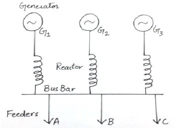
When reactor is connected between bus bar and generator, it is called a generator reactor. This reactor can also be connected in series with the generator. When a new generator is connected with an old generator, a reactor is added in series with the old generator to provide protection. The value of this reactor depends on the impedance of that generator. Its pu value should be 0.05 or 0.06. See the following figure:

Generator reactors

Disadvantages:

  1. The fault on a feeder disconnects the supply of other feeders also.
  2. After removing the faulty feeder, the generator has to be synchronized again.
  3. During normal operation, full load current passes through the reactor which causes continuous power loss.

Feeder reactors:

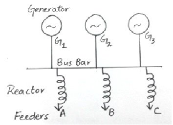
It is when a reactor is connected in series with a feeder as shown in the figure:

feedder reactors

Usually short circuits occur on feeders therefore, feeder reactors are very important. In the absence of feeder reactors, if a fault occurs on the nearest generating station, the bus bar voltage will be reduced to zero and the connected generators will lose their synchronism.

Advantages:

  1. The voltage drop across a reactor during faulty conditions will not affect the voltage of bus bar, therefore, there are less chances of losing synchronism.
  2. A fault on a feeder will not affect any other feeder.

Disadvantages:

  1. Every feeder needs a reactor hence the number or reactors increases.
  2. If the number of generators increases, then the size of the reactor should also be increased.
  3. During normal operation, full load current passes through the reactor which causes continuous power loss.

Reactors should be connected according to the power factor of the feeders to regulate proper voltages. Feeder reactance should be about 0.05 to 0.12 pu.

  1. Bus bar reactors:

These reactors are connected with bus bars. Bus bar reactors divide the bus bar in smaller sections. If the voltage level is same, no current passes through these reactors and every section act as an independent bus bar.

If a fault occurs on a section of bus bar, the reactor prevents the fault from reaching to other sections and only the fault section is affected. Hence a bus bar should be large enough to protect the system but it should not disturb the synchronism of the system. A reactor which drops the voltage about 30 to 50% at full current is suitable. However the reactance of a sinlge bus bar reactor should be about 0.3 to 0.5 pu.

The following methods describe how to decrease the continuous voltage drop and power losses in case of feeder and generator reactors:

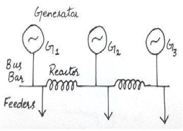
  1. Ring system:

In this system, a bus bar is divided into different sections and these sections are connected together through a reactor. Each feeder is fed by a separate generator and during normal operation each generator supplies power to its respective load due to which very less power loss occurs in the reactors.

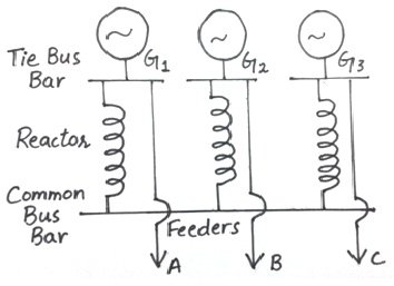
reactors in ring system     2. Tie bar system:

In this system, the generators are connected to a common bus bar through the reactors and feeders are fed through the generator side of the reactors. This system is very efficient in case of larger systems. The reactance of the reactors in this case is half as compared to the ring system reactance.

reactors in tie bar system

Advantages and disadvantages:

This system is more flexible. By increasing the number of sections, the switch gears work efficiently without any modifications in the system.

But this system is complex and requires an additional bus i.e, tie bar.

Monday 14 November 2022

Concept of excitation systems in modern alternator (Excitation System)


Definition: The system which is used for providing the necessary field current to the rotor winding of the synchronous machine, such type of system is called an excitation system. In other words, excitation system is defined as the system which is used for the production of the flux by passing current in the field winding. The main requirement of an excitation system is reliability under all conditions of service, a simplicity of control, ease of maintenance, stability and fast transient response.

The amount of excitation required depends on the load current, load power factor and speed of the machine. The more excitation is needed in the system when the load current is large, the speed is less, and the power factor of the system becomes lagging.

Types of Excitation System

The excitation system is mainly classified into three types. They are

  1. DC Excitation System
  2. AC Excitation System
    • Rotor Excitation System
    • Brushless Excitation System
  3. Static Excitation System

1. DC Excitation System

The DC excitation system has two exciters – the main exciter and a pilot exciter. The exciter output is adjusted by an automatic voltage regulator (AVR) for controlling the output terminal voltage of the alternator. The current transformer input to the AVR ensures limiting of the alternator current during a fault.

When the field breaker is open, the field discharge resistor is connected across the field winding so as to dissipate the stored energy in the field winding which is highly inductive.

The main and the pilot exciters can be driven either by the main shaft or separately driven by the motor. Direct driven exciters are usually preferred as these preserve the unit system of operation, and the excitation is not excited by external disturbances.

The voltage rating of the main exciter is about 400 V, and its capacity is about 0.5% of the capacity of the alternator. Troubles in the exciters of turbo alternator are quite frequent because of their high speed and as such separate motor driven exciters are provided as standby exciter.

2. AC Excitation System

The AC excitation system consists of an alternator and thyristor rectifier bridge directly connected to the main alternator shaft. The main exciter may either be self-excited or separately excited. The AC excitation system may be broadly classified into two categories which are explained below in details.

a. Rotating Thyristor Excitation System

The rotor excitation system is shown in the figure below. The rotating portion is being enclosed by the dashed line. This system consists an AC exciter, stationary field and a rotating armature. The output of the exciter is rectified by a full wave thyristor bridge rectifier circuit and is supplied to the main alternator field winding.


The alternator field winding is also supplied through another rectifier circuit. The exciter voltage can be built up by using it residual flux. The power supply and rectifier control generate the controlled triggering signal. The alternator voltage signal is averaged and compare directly with the operator voltage adjustment in the auto mode of operation. In the manual mode of operation, the excitation current of the alternator is compared with a separate manual voltage adjustment.

b. Brushless Excitation System

This system is shown in the figure below. The rotating portion being enclosed by a dashed line rectangle. The brushless excitation system consists an alternator, rectifier, main exciter and a permanent magnet generator alternator. The main and the pilot exciter are driven by the main shaft. The main exciter has a stationary field and a rotating armature directly connected, through the silicon rectifiers to the field of the main alternators.


The pilot exciter is the shaft driven permanent magnet generator having rotating permanent magnets attached to the shaft and a three phase stationary armature, which feeds the main exciter field through silicon rectifiers, in the field of the main alternator. The pilot exciter is a shaft driven permanent magnetic generator having rotating permanent magnets attached to the shaft and a 3-phase stationary armature, which feeds the main’s exciter through 3-phase full wave phase controlled thyristor bridges.

The system eliminates the use of a commutator, collector and brushes have a short time constant and a response time of fewer than 0.1 seconds. The short time constant has the advantage in improved small signal dynamic performance and facilitates the application of supplementary power system stabilising signals.

3. Static Excitation System

In this system, the supply is taken from the alternator itself through a 3-phase star/delta connected step-down transformer. The primary of the transformer is connected to the alternator bus and their secondary supplies power to the rectifier and also feed power to the grid control circuit and other electrical equipment.

This system has a very small response time and provides excellent dynamic performance. This system reduced the operating cost by eliminating the exciter windage loss and winding maintenance.


Monday 31 October 2022

Power factor correction/improvement


Power factor correction

Power factor basics:

Power quality is essential for efficient equipment operation, and power factor contributes to this.

Power factor is the measure of how efficiently incoming power is used in an electrical installation. It is the ratio of active to apparent power, when:

  • Active Power (P) = the power needed for useful work such as turning a lathe, providing light or pumping water, expressed in Watt or KiloWatt (kW)
  • Reactive Power (Q) = a measure of the stored energy reflected to the source which does not do any useful work, expressed in var or Kilovar (kVAR)
  • Apparent Power (S) = the vector sum of active and reactive power, expressed in Volt Amperes or in KiloVolt Amperes (kVA)
  • The power triangle:

    Poor power factor (for example, less than 95%) results in more current being required for the same amount of work.

    Power factor correction

    Power factor correction is obtained via the connection of capacitors which produce reactive energy in opposition to the energy absorbed by loads such as motors, locally close to the load. This improves the power factor from the point where the reactive power source is connected, preventing the unnecessary circulation of current in the network.

    Determining the power factor correction required

    • Calculation of the required reactive power

    1st step we have to determine the required reactive power (Qc (kvar)) to be installed to  improve power factor (cos φ) and reduces the apparent power (S).

    Qc can be determined from the formula Qc = P (tan φ – tan φ‘), which is deduced from the diagram.

  • Qc = power of the capacitor bank in kVAr
  • P = active power of the load in kW
  • tan φ = tangent of phase shift angle before compensation
  • tan φ’ = tangent of phase shift angle after compensation
  • The parameters φ and tan φ can be obtained from billing data, or from direct measurement in the installation.

    Step 2: Selection of the compensation mode

    The location of low-voltage capacitors in an installation can either be central (one location for the entire installation), by sector (section-by-section), at load level, or a combination of the latter two.

    In principle, the ideal compensation is applied at a point of consumption and at the level required at any moment in time. In practice, technical and economic factors govern the choice.

    The location is determined by:

  • the overall objective (avoiding penalties on reactive energy, relieving transformers or cables, avoiding voltage drops and sags)
  • the operating mode (stable or fluctuating loads)
  • the foreseeable influence of capacitors on the network characteristics
  • the installation cost
  • Step 3: Selection of the compensation type

    Different types of compensation should be adopted depending on the performance requirements and complexity of control:

  • Fixed, by connection of a fixed-value capacitor bank
  • Automatic, by connection of a different number of steps, allowing adjustment of the reactive energy to the required value
  • Dynamic, for compensation of highly fluctuating loads
  • Step 4: Allowance for operating conditions and harmonics

    Operating conditions have a great impact on the life expectancy of capacitors, so the following parameters should be taken into account:

  • Ambient temperature (°C)
  • Expected over-current related to voltage disturbances, including maximum sustained overvoltage
  • Maximum number of switching operations per year
  • Required life expectancy
  • Some loads (variable speed motors, static converters, welding machines, arc furnaces, fluorescent lamps, etc.) pollute the electrical network by reinjecting harmonics. It is therefore also necessary to consider the effects of these harmonics on the capacitors.

    The benefits of power factor correction

    Savings on the electricity bill

    Power factor correction eliminates penalties on reactive energy, decreases demand on kVA, and reduces power losses generated in the transformers and conductors of the installation.

    Increased available power

    Fitting PFC equipment on the low voltage side increases the power available at the secondary of a MV/LV transformer. A high power factor optimises an electrical installation by allowing better use of the components.

    Reduced installation size

    Installing PFC equipment allows conductor cross-section to be reduced, as less current is absorbed by the compensated installation for the same active power.

    Reduced voltage drops

    Installing capacitors allows voltage drops to be reduced upstream of the point where the PFC device is connected, therefore preventing overloading of the network and reducing harmonics.


    Why we connect Capacitor in parallel, not in series?


    Reason 1

    We know that in series connection Current is constant and voltage is varying but in parallel connection, voltage is constant and current is varying. 
    So we need to keep constant the voltage across the load. So if we connect a capacitor in parallel it will be drawn leading current according to its rated value. But if we connect a capacitor in parallel then the flow of current through the capacitor will depend on the load.


    Reason 2

    As in the case of series connection of capacitor current fully depends upon the load so we need a capacitor of high value which can deliver the full load current.


    Reason 3

    If we connect a capacitor in series with the load for power factor improvement then a voltage will be dropped by the capacitor.


    Reason 4

    If we connect the capacitor in series with the load then if short circuit fault occurs in the load then the total voltage will be applied to the capacitor which may blow them.


    Reason 5

    In case of series connection, if we want to connect additional capacitor then we need to open the whole circuit. But in case of parallel connection, we can easily connect an additional capacitor in parallel with the existing capacitor.


    Reason 6

    If we connect the capacitor in series with the load for power factor improvement then the recovery voltage across the contacts of the switchgear shall be high.

    Types of source

      Ideal Voltage Source:  An ideal voltage source is capable to maintain the constant voltage across its terminals. The voltage across the vo...

    Translate