Wednesday 11 May 2022

Transposition of conductors in Power Transmission Lines


Transposition of conductors in Power Transmission Lines

Parameters of Transmission Line:

A transmission line has four parameters, namely resistance, inductance, capacitance and conductance. The resistance ‘R’ of a line is because of conductor resistance, series inductance ‘L’ is due to the magnetic field surrounding the conductors, shunt capacitance ‘C’ is due to the electric field between conductors, and shunt conductance, ‘G’ is because of the leakage current between phases and ground.

What is Transposition of Conductors?

The interchange of conductor positions of a transmission line at regular intervals along the route is known as Transposition of Conductors.

Why transposition is needed?

In the power transmission line when the line conductors are asymmetrically spaced i.e. not equally spaced, the inductance of each phase is different causing voltage drops of different magnitudes in the three phases even if the system is operating under balanced condition (load currents are balanced in the three phases). Also the magnetic field external to the conductors is not zero thereby inducing voltages in adjacent communication lines and causing what is known as “telecommunication interference”. This can be overcome by the interchange of conductor positions at regular intervals along the route and this practice is known as “transposition of conductors”.

How transposition is done?

In a transposed transmission line each of the three conductors occupies all the three positions relative to other conductors (position 1, position 2, and position 3) for one-third of the total length of the transmission line. Transposition also balances out the line capacitance so that electro-statically induced voltages are also balanced. Figure shows the transposition of conductors over a complete cycle.


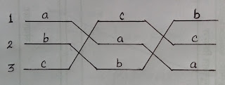
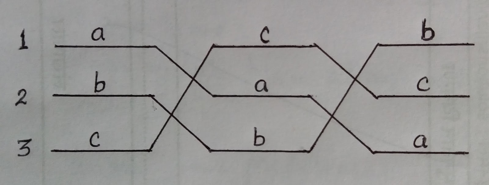
A complete cycle of transposition of line conductors.


Complications of Conductor Transposition:

Frequent transposition usually leads to complication of support structures (as can be seen by the picture below), increase the cost because of increased number of insulator strings and total weight of supports. 
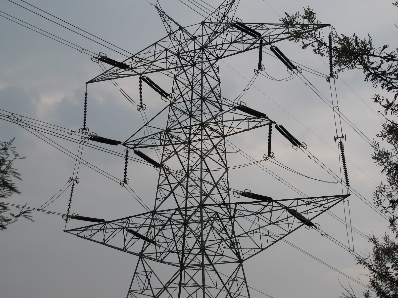
Transposition on 400 kV, double circuit transmission line, near Bhopal, M.P. 

Disadvantage of Transposition

Frequently changing the position of conductors weakens the supportive structure which increases the cost of the system. 

Kirchhoffs Circuit Law


Kirchhoffs First Law – The Current Law, (KCL)

Kirchhoffs Current Law or KCL, states that the “tthe algebraic sum of flowing currents through a point (or junction) in a network is Zero (0) or in any electrical network, the algebraic sum of the currents meeting at a point (or junction) is Zero (0)“. I(exiting) + I(entering) = 0. This idea by Kirchhoff is commonly known as the Conservation of Charge.

Kirchhoffs Current Law

kirchhoffs current law


Here, the three currents entering the node, I1, I2, I3 are all positive in value and the two currents leaving the node, I4 and I5 are negative in value. Then this means we can also rewrite the equation as;

I1 + I2 + I3 – I4 – I5 = 0

The term Node in an electrical circuit generally refers to a connection or junction of two or more current carrying paths or elements such as cables and components. Also for current to flow either in or out of a node a closed circuit path must exist. We can use Kirchhoff’s current law when analysing parallel circuits.

Kirchhoffs Second Law – The Voltage Law, (KVL)

Kirchhoffs Voltage Law or KVL, states that “in any closed loop network, the total voltage rise in the loop is equal to the sum of all the voltage drops within the same loop”. In other words the algebraic sum of all voltages within the loop must be equal to zero. This idea by Kirchhoff is known as the Conservation of Energy.

Kirchhoffs Voltage Law


Starting at any point in the loop continue in the same direction noting the direction of all the voltage drops, either positive or negative, and returning back to the same starting point. It is important to maintain the same direction either clockwise or anti-clockwise or the final voltage sum will not be equal to zero. We can use Kirchhoff’s voltage law when analysing series circuits.

Determination of signs while solving problems-

Voltage Source: A positive sign is assigned to the
 EMF when going from the negative terminal of the 
voltage source to the positive terminal since there is 
an increase in potential. On the other hand, when moving
 from the positive terminal to the negative terminal,
 potential drops and the EMF is marked as negative.

2.  Resistance: The potential drop is negative when passing through

 the resistance in the same direction as the current flow because

 the potential decreases. However, if the resistance is traversed

 in the opposite direction to the current flow, the potential increases,

resulting in a positive voltage drop.


Friday 6 May 2022

Corona


What is corona?

There are two types of transmission lines, overhead lines, and underground lines. We all know that; the overhead lines operate at high voltage to reduce the transmission loss. therefore, a very high amount of electric field produced between the conductors.

In overhead transmission lines, the conductors place in free air. Hence, the air acts as the dielectric medium between the conductors.

The dielectric strength of air at normal temperature and pressure is 30 kV/cm.

If the voltage between conductors is high, it causes the potential gradient between the conductors to exceed this value. In this condition, the breakdown of air will take place. And the air is ionized and current will flows through it.

The potential gradient value between conductors reaches 30 kV/cm, the air in the vicinity of the conductor becomes conducting and a hissing sound heard and some vibration produced in the conductor.

Around the conductor, a dark violet glow occurs with a hissing noise. During this process, ozone gas produced.

This entire process is known as the corona.

Corona loss in transmission line

Corona appears in the transmission line when the surface voltage gradient at the line conductor reaches the breakdown stress. Due to corona, heat and bluish light produce. There is a loss of power and energy dissipation. This loss is known as the corona loss.

The efficiency of the transmission line decreased due to corona loss.

There is also a minor effect on the voltage regulation of the transmission line. But this is always negligible.

In normal and fair atmospheric conditions, the corona loss can vary between few kW/km lengths of the conductor in Extra high voltage transmission line.

Particularly in a thunderstorm, the corona loss is very high. It can be hundreds of kW/km in bad weather conditions.

Factors affecting corona loss

1) Atmospheric condition

The corona loss occurs due to the ionization of air between the conductors. In stormy weather conditions, the rainy condition number of ions in the air between the conductors will be more. Hence, chances of corona occurrence will increase.

2) The physical condition of the conductor

  • Line voltage: If the line voltage is more, the electric field between the conductor is more. Hence the chance of corona occurrence is more. In a low voltage transmission line, there is less chance of corona.
  • Ratio D/r: ‘D’ is the distance between the conductors and ‘r’ is the radius of the conductor. If the distance between the conductor is more compared to the radius, the possibility of the corona is reduced. The strength of the electrostatic field reduced because of the large spacing between the conductors.
  • Nature of conductor surface: The rough and irregular surface of the conductor gives rise to more corona. Stranded conductors give rise to more corona compare to the circular conductor.
  • The roughness of conductor: Surface causes field distortion and high voltage gradient developed in the local area of the conductor. Thus, the chance of the occurrence of the corona is more.

3) Effect of the frequency

Corona is directly proportional to the supply frequency.

4) Effect of density of air

Corona is intentionally proportional to the density of air. Density is lower in the hilly area. Hence, in this area more chance of the corona.

5) Effect of air conductivity

Higher conductivity leads to higher corona.

Methods to reduce the corona effect

  • The corona effect can be reduced by increasing the radius of the conductor or by increasing the distance between the conductors. The spacing between the conductor cannot increase beyond a certain level. Therefore, increase the radius of the conductor to reduce the corona effect.
  • The open parts like a clamp, support, etc. are designed with a smooth surface.
  • Operating the line at lower voltage reduces the corona loss.

Skin Effect

 Skin Effect

The non-uniform distribution of electric current over the surface or skin of the conductor carrying a.c is called the skin effect. In other words, the concentration of charge is more near the surface as compared to the core of the conductor. The ohmic resistance of the conductor is increased due to the concentration of current on the surface of the conductor.

Skin effect increases with the increase in frequency. At low frequency, such as 50Hz, there is a small increase in the current density near the surface of the conductor; but, at high frequencies, such as radio frequency, practically the whole of the currents flows on the surface of the conductor. If d.c current (frequency=0) is passed in a conductor, the current is uniformly distributed over the cross-section of the conductors.

skin-effect

Why skin effect occurs?

Let us consider the conductor is made up of a number of concentric cylinders. When a.c is passed in a conductor, the magnetic flux induces in it. The magnetic flux linking a cylindrical element near the center is greater than that linking another cylindrical element near the surface of the conductor. This is due to the fact that the center cylindrical element is surrounded by both the internal as well as the external flux, while the external cylindrical element is surrounded by the external flux only.

The self-inductance in the inner cylindrical element is more and, therefore, will offer a greater inductive reactance than the outer cylindrical element. This difference in the inductive reactance gives a tendency to the current to concentrate towards the surface or skin of the conductor.

The current density is maximum at the surface of the conductor and minimum at the center of the conductor. The effect is equivalent to a reduction of the cross-section area of the conductor and, therefore the effective resistance of the conductor is increased.

Factors affecting skin effect

  1. Frequency – Skin effect increases with the increase in frequency.
  2. Diameter – It increases with the increase in diameter of the conductor.
  3. The shape of the conductor – Skin effect is more in the solid conductor and less in the stranded conductor because the surface area of the solid conductor is more.
  4. Type of material – Skin effect increase with the increase in the permeability of the material (Permeability is the ability of material to support the formation of the magnetic field).

Points-to-remember

  1. The Skin effect is negligible if the frequency is less than the 50Hz and the diameter of the conductor is less than the 1cm.
  2. In the stranded conductors like ACSR (Aluminium Conductor Steel Reinforced) the current flows mostly in the outer layer made of aluminum, while the steel near the center carries no current and gives high tensile strength to the conductor. The concentration of current near the surface enabled the use of ACSR conductor.

Main Components of Overhead Lines and choice of conductors

 Main Components 
& Conductor Materials Used in Overhead Lines

Main Components of Overhead Lines

An overhead line may be used to transmit or distribute electric power. The successful operation of an overhead line main Components of Overhead Lines depends to a great extent upon the mechanical design of the line. While constructing an overhead line, it should be ensured that the mechanical strength of the line is such so as to provide against the most probable weather conditions.

Conductors :

The lines used for the transmission and distribution of electricity are called conductors. The conductor is mainly used to carry the electrical energy from the generating station to the distribution substation and from the distribution centre to the consumer load centres. Conductors are the most expensive component in the overhead line transmission as the different parameters are taken into consideration for the material selection of the conductor. The size, shape and type of material used are the main factors in selecting conductors.

During the material selection, the current rating and the span of current-carrying factors will play a key role such as they will decide the type of composition that should be used for the conductors. The type of materials used for the conductors are:

a. Copper: The main factor of using copper is that it holds the highest conductivity factor. The most commonly used material for the conductors is copper. There are mainly three kinds of copper such as soft-drawn, medium-drawn and Hard-drawn. The hard drawn copper is used for the construction of the conductors. The main factors for selecting hard drawn copper as it has less elastic factor and more mechanical strength which will make the conductor withstand high current. Due to expensive factors, copper is not directly used for overhead transmission.

b. Aluminium: the most commonly used conductors are made up of aluminium as it is less costly. The weight is also lighter compared to the copper, this advantage makes the pole strength factor decreases. ACSR and AAAC conductors are mainly used for the transmission lines. ACSR is made up of small strands of aluminium twisted together used for the conductors. The twisting of the aluminium strands will give more tensile strength which is used to withstand heavy currents. The main disadvantage of aluminium is it has less conductivity compared to copper and less tensile strength.

c. Galvanized Steel: the major advantage of Galvanized steel is it is cost-effective. It is used for short-distance power transmissions as it consists of some drawbacks such as low conductivity, high resistance and less tensile strength.

d. Cadmium Copper and Copper weld steel are rarely used because of their most expensive factor.

Insulators :

Insulators are provided on the supports (poles or towers) to support conductors such that necessary insulation is provided to supports from conductors. This further prevents leakage currents from conductor to earth through supports. Insulators also prevent short-circuiting between conductors and metalwork. The most commonly used insulating materials are porcelain, glass, and Stealite. The various types of insulators are,

Pin-type insulators
Suspension type insulators
Strain insulators
Shackle insulators and
Stay insulators.

Supports :

The function of line supports is to support the conductors and to keep the conductors at a suitable level above the ground. Generally, poles or towers are chosen as supports. These are employed depending upon the working voltage and the regions where they are used. Poles or towers are of various types like,

Wooden poles
Steel poles
RCC poles and
Lattice steel towers.

Cross-arms and Clamps :

These are provided on pole structures to support the insulators and conductors. These are made up of either wood or steel angle sections.


Guys and Stays :

These are employed to resists the lateral forces at the termination or angle poles by fastening the braces or cables to the poles.


Lightning Arrestors :

It is a device used to provide protection against traveling waves or high voltage produce due to lightning by discharging the excessive-high voltage of the line to the ground.

Fuses and Isolating Switches :

These are used to isolate different parts of the transmission system.

Earth Wire :

Earth wire is made run on the top of the towers in order to protect the line against lightning.

Vee-Guards :

To ensure public safety, these are provided below the base overhead line along the street.

Guard Wires :

The guard wires are provided above or below transmission lines while crossing the communication lines and are solidly connected to the earth.

Miscellaneous Components :

Phase plates, bird guards, danger plates, barbed wires, vibration-dampers, top hampers, beads for jumpers, etc. The phase plates give information about various phases used, the barbed wire, and are wounded to poles at a height of 2.5 meters in order to prevent the climbing of unauthorized persons. However, danger plates are also provided at a height of 2.5 meters from the ground level.


Voltage Source and Current Source – Ideal vs. Practical


Voltage Source and Current Source – Ideal vs. Practical

Voltage source:

Ideal Voltage Source: 

A voltage source is a device which provides a constant voltage to load at any instance of time and is independent of the current drawn from it. This type of source is known as an ideal voltage source. It has zero internal resistance.

            The graph represents the change in voltage of the voltage source with respect to time. It is                 constant at any instance of time.

Practical Voltage Source:

Voltage sources that have some amount of internal resistance are known as a practical voltage source. Due to this internal resistance, voltage drop takes place. If the internal resistance is high, less voltage will be provided to load and if the internal resistance is less, the voltage source will be closer to an ideal voltage source.A practical voltage source is thus denoted by a resistance in series which represents the internal resistance of source.
 

Current source:

 Ideal Current Source:
A current source is a device which provides the constant current to load at any time and is independent of the voltage supplied to the circuit. This type of current is known as an ideal current source; practically ideal current source is also not available. It has infinite resistance. 

The graph represents the change in current of the current source with respect to time. It is constant at any instance of time.

Practical Current source

Practically current sources do not have infinite resistance across there but they have a finite internal resistance. So the current delivered by the practical current source is not constant and it is also dependent somewhat on the voltage across it.

A practical current source is represented as an ideal current source connected with resistance in parallel.

The graph represents the current of the current source with respect to time. It is not constant but it also keeps on decreasing as the time passes.


Monday 18 April 2022

Design of Lighting Schemes

 i. Illumination Level:

This is the most vital factor because a sufficient illumination is the basic means whereby we are able to see our surroundings.

For each type of work there is a range of brightness most favourable to output i.e. which causes minimum fatigue and gives maximum output in terms of quality depends upon:

(i) The size of the objects to be seen and its distance from the observer. Greater the distance of the object from observer and smaller the size of the object, greater will be the illumination required for its proper perception and

(ii) Contrast between the object and back-ground-greater the contrast between the colour of the object and its background, greater will be the illumination required to distinguish the object properly. Objects which are seen for longer duration of time required more illumination than those for casual work. Similarly moving objects required more illumination than those for stationary objects.

ii. Uniformity of Illumination:

The human eye adjusts itself automatically to the brightness within the field of vision. If there is a lack of uniformity, pupil or iris of the eye has to adjust more frequently and thus fatigue is caused to the eye and productivity is reduced. It has been found that visual performance is best if the range of brightness within the field of vision is not greater than 3:1, which can be achieved by employing general lighting.

iii. Shadows:

In lighting installations, formation of long and hard shadows causes fatigue of eyes and therefore is considered to be a shortcoming. Complete absence of shadows altogether again does not necessarily mean an ideal condition of lighting instillations. Contrary, perhaps to popular opinion, a certain amount of shadow is desirable in artificial lighting as it helps to give shape to the solid objects and makes them easily recognised.

iv. Glare:

It may be direct or reflected i.e. it may come direct from the light source or it may be reflected brightness such as from a desk top, nickeled machine parts, or calendared paper.

Direct glare from a source of light is more common, and is more often a hindrance to vision. A glance at the sun proves that an extremely bright light source causes acute eye discomfort. Reflected glare is glare which comes to the eyes as glint or reflection of the light source in some polished surface.

v. Mounting Height:

In case of direct lighting it depends upon the type of building and type of lighting scheme employed. For rooms of large floor area, the luminaries should be mounted close to ceiling as possible. In case of indirect and semi-indirect lighting, it would be desirable to suspend luminaries enough down from ceiling to give uniform illumination.

vi. Spacing of Luminaries:

The distance of light source from the wall should be equal to one half the distances between two adjacent light sources. The distance between light fittings should not exceed 1.5 times the mounting height.

Types of source

  Ideal Voltage Source:  An ideal voltage source is capable to maintain the constant voltage across its terminals. The voltage across the vo...

Translate