Friday 20 May 2022

Superposition Theorem

 Superposition Theorem 

    Superposition Theorem state that in any linear bilateral network having more than one source, the response in any one of the element is equal to algebraic sum of the response caused by individual source while rest of the sources are replaced by their internal resistances.

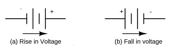
1.We consider one independent source at a time while all other independent sources are turned off. This implies that we replace voltage source by short circuit and current source by open circuit. This way we obtain a simpler and more manageable circuit.

2.Turn off all independent sources except one source. Find the output (voltage or current) due to that active source.

3.Repeat  the above step for each of the other independent sources.

4.Find the total contribution by adding algebraically all the contributions due to the independent sources.

Consider the following linear circuit with two sources: one current source and one voltage source. The two sources are the inputs to the function. For this problem we happen to want to find two outputs, currents i, start subscript, 1, end subscript and i, start subscript, 2, end subscript.

Let’s analyze this circuit using superposition.
First, we suppress the current source and analyze the circuit with just the voltage source acting alone. To suppress the current source, we replace it with an open circuit.

With just the voltage source, the two output currents are:
i, start subscript, 1, V, end subscript, equals, 0, i, start subscript, 2, V, end subscript, equals, start fraction, start text, V, s, end text, divided by, start text, R, end text, 2, end fraction
Where i, start subscript, 1, V, end subscript and i, start subscript, 2, V, end subscript are the currents in start text, R, end text, 1 and start text, R, end text, 2 caused by the voltage source.

Next, we restore the current source and suppress the voltage source, to calculate the contribution of the current source acting alone.

With just the current source, the two output currents are:
Where i, start subscript, 1, I, end subscript and i, start subscript, 2, I, end subscript are the currents in start text, R, end text, 1 and start text, R, end text, 2 caused by the current source. 
We complete the analysis by adding the contributions from each source:
i, start subscript, 1, end subscript, equals, i, start subscript, 1, V, end subscript, plus, i, start subscript, 1, I, end subscript, equals, 0, plus, start text, I, s, end text, equals, start text, I, s, end text

Wednesday 11 May 2022

Transposition of conductors in Power Transmission Lines


Transposition of conductors in Power Transmission Lines

Parameters of Transmission Line:

A transmission line has four parameters, namely resistance, inductance, capacitance and conductance. The resistance ‘R’ of a line is because of conductor resistance, series inductance ‘L’ is due to the magnetic field surrounding the conductors, shunt capacitance ‘C’ is due to the electric field between conductors, and shunt conductance, ‘G’ is because of the leakage current between phases and ground.

What is Transposition of Conductors?

The interchange of conductor positions of a transmission line at regular intervals along the route is known as Transposition of Conductors.

Why transposition is needed?

In the power transmission line when the line conductors are asymmetrically spaced i.e. not equally spaced, the inductance of each phase is different causing voltage drops of different magnitudes in the three phases even if the system is operating under balanced condition (load currents are balanced in the three phases). Also the magnetic field external to the conductors is not zero thereby inducing voltages in adjacent communication lines and causing what is known as “telecommunication interference”. This can be overcome by the interchange of conductor positions at regular intervals along the route and this practice is known as “transposition of conductors”.

How transposition is done?

In a transposed transmission line each of the three conductors occupies all the three positions relative to other conductors (position 1, position 2, and position 3) for one-third of the total length of the transmission line. Transposition also balances out the line capacitance so that electro-statically induced voltages are also balanced. Figure shows the transposition of conductors over a complete cycle.


A complete cycle of transposition of line conductors.


Complications of Conductor Transposition:

Frequent transposition usually leads to complication of support structures (as can be seen by the picture below), increase the cost because of increased number of insulator strings and total weight of supports. 
Transposition on 400 kV, double circuit transmission line, near Bhopal, M.P. 

Disadvantage of Transposition

Frequently changing the position of conductors weakens the supportive structure which increases the cost of the system. 

Kirchhoffs Circuit Law


Kirchhoffs First Law – The Current Law, (KCL)

Kirchhoffs Current Law or KCL, states that the “tthe algebraic sum of flowing currents through a point (or junction) in a network is Zero (0) or in any electrical network, the algebraic sum of the currents meeting at a point (or junction) is Zero (0)“. I(exiting) + I(entering) = 0. This idea by Kirchhoff is commonly known as the Conservation of Charge.

Kirchhoffs Current Law

kirchhoffs current law


Here, the three currents entering the node, I1, I2, I3 are all positive in value and the two currents leaving the node, I4 and I5 are negative in value. Then this means we can also rewrite the equation as;

I1 + I2 + I3 – I4 – I5 = 0

The term Node in an electrical circuit generally refers to a connection or junction of two or more current carrying paths or elements such as cables and components. Also for current to flow either in or out of a node a closed circuit path must exist. We can use Kirchhoff’s current law when analysing parallel circuits.

Kirchhoffs Second Law – The Voltage Law, (KVL)

Kirchhoffs Voltage Law or KVL, states that “in any closed loop network, the total voltage rise in the loop is equal to the sum of all the voltage drops within the same loop”. In other words the algebraic sum of all voltages within the loop must be equal to zero. This idea by Kirchhoff is known as the Conservation of Energy.

Kirchhoffs Voltage Law


Starting at any point in the loop continue in the same direction noting the direction of all the voltage drops, either positive or negative, and returning back to the same starting point. It is important to maintain the same direction either clockwise or anti-clockwise or the final voltage sum will not be equal to zero. We can use Kirchhoff’s voltage law when analysing series circuits.

Determination of signs while solving problems-

Voltage Source: A positive sign is assigned to the
 EMF when going from the negative terminal of the 
voltage source to the positive terminal since there is 
an increase in potential. On the other hand, when moving
 from the positive terminal to the negative terminal,
 potential drops and the EMF is marked as negative.

2.  Resistance: The potential drop is negative when passing through

 the resistance in the same direction as the current flow because

 the potential decreases. However, if the resistance is traversed

 in the opposite direction to the current flow, the potential increases,

resulting in a positive voltage drop.


Types of source

  Ideal Voltage Source:  An ideal voltage source is capable to maintain the constant voltage across its terminals. The voltage across the vo...

Translate